Code Verification Using PIL Simulation on Infineon AURIX TC4x Microcontrollers for ISO 26262 Certification
This example shows how to verify generated code on an Infineon AURIX™ TC4x hardware board using processor-in-the-loop (PIL) simulation. The example uses a Model-Based Design example from the IEC Certification Kit.
Model-Based Design enables fast and cost-effective development of dynamic systems such as control, signal processing, and communications systems. You can use software-in-the-loop (SIL) and PIL simulations to verify that your model components and the generated production code produce numerically equivalent results. IEC Certification Kit provides documents that help you to map Model-Based Design use cases to requirements from functional safety standards and automotive standards such as ISO 26262.
This example shows how to configure the IEC Certification Kit example model for Infineon AURIX TC4x hardware board and use Simulink Test Manager for source code verification using PIL simulations.
Prerequisites
Complete the following examples and tutorials:
Required Hardware
Infineon AURIX TC4xx hardware board
Micro-USB cable
Open Model-Based Design Example from IEC Certification Kit
This example uses model and test cases included with the High-Voltage Battery System: A Model-Based Design Example for Automotive SPICE and ISO 26262:2018 (IEC Certification Kit) example.
Open the example project in MATLAB®.
openExample("iec_certkit/CertAutosarExample");
You can generate simulation-based tests and load them into Simulink Test Manager for equivalence testing. For more information, see Create a Test Harness (Simulink Test).
For this example, execute this command to open Simulink Test Manager pre-loaded with tests from the battery system example.
open('ArStateMachine_Test.mldatx');
Configure Model for Infineon AURIX Microcontroller
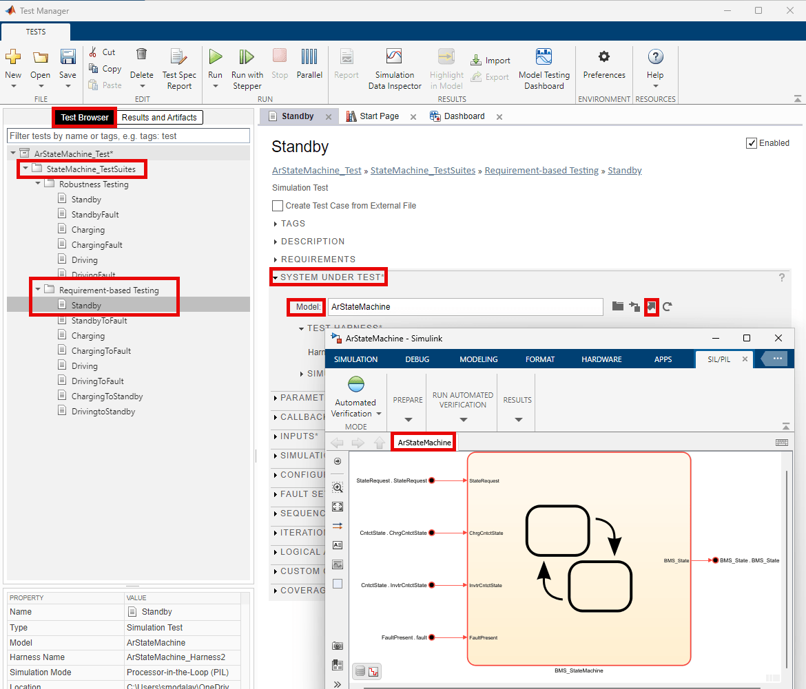
1. In the Test Manager window, under Test Browser, expand StateMachine_TestSuites.
2. Under Requirement-based Testing, click Standby.
3. Under System Under Test, go to Model and click arrow button to open the ArStateMachine model.
4. To open the Configuration Parameters dialog box, in the Simulink Toolstrip, on the Modeling tab, click Model Settings. To open the referenced Configuration Parameters dialog box, click gear button.
5. In the Hardware Implementation pane, set Hardware board to Infineon AURIX TC4x.
6. In the Hardware Implementation pane, expand Target hardware resources. On the Connectivity tab, specify the Serial port in MATLAB preferences parameter. To find the COM port number of the USB Serial Port showing in your host computer, open Device Manager window and expand Ports (COM & LPT).
7. Expand the Code Generation pane and select Verification. Under Code coverage for SIL or PIL, select Enable portable word sizes. Click Apply.

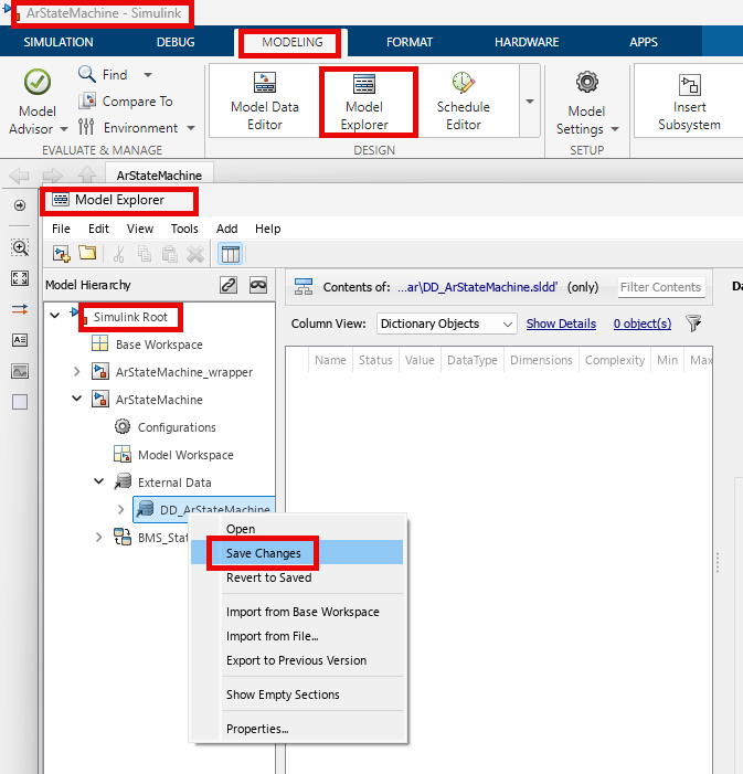
8. To save the configuration parameter settings in the Data Dictionary, in the Simulink Toolstrip, on the Modeling tab, click Model Explorer.
In the Model Explorer window, under Simulink Root, expand ArStateMachine and External Data pane. Right-click DD_ArStateMachine and select Save Changes.
Verify target connectivity
Verify the connectivity, automated code generation, compilation, linking and downloading of the object code to the target hardware by performing PIL simulations in the SIL/PIL manager.
1. To launch the SIL/PIL Manager app, in the Simulink Toolstrip, on the Apps tab, select SIL/PIL Manager.
2. On the SIL/PIL tab, set Mode to Automated Verification and SIL/PIL Mode to Processor-in-the-Loop (PIL). Click Run Verification.

Run PIL Simulation in Simulink Test Manager
You can modify the simulation settings in the Simulink Test Manager to enable PIL simulation as part of the requirement-based testing workflow.
1. In the Simulink Test manager window, under Test Browser, expand StateMachine_TestSuites.
2. In the Requirement-based Testing pane, select Standby.
3. Under System Under Test, in the Test Harness, set Harness to ArStateMachine_Harness2.
4. Expand Simulation Settings and Release Overrides and set the Simulation Mode to Processor-in-the-Loop (PIL).
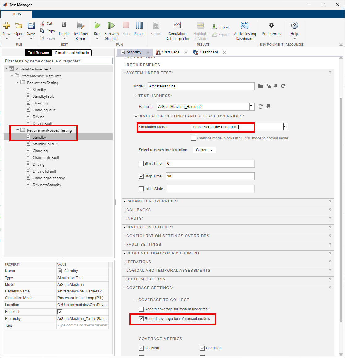
5. On the Test Manager toolbar, click Save to save these settings. Click Run to execute the test.
6. To review the execution results and summary of the coverage results after completion of the PIL simulation, in the Simulink Test manager window, go to Results and Artifacts tab. Under Results pane, select Standby.

Known Limitations
TASKING® SmartCode for TriCore does not support the code coverage functionality in PIL Simulations. For more information on the supported compilers, see Supported Hardware and Required Software.
Other Things to Try
To perform back-to-back equivalence testing and identify coverage gaps, perform SIL simulation with the similar setup and compare generated code for both SIL and PIL simulations. For more information, see SIL, PIL, and HIL Tests (Simulink Test) and Back-to-Back Equivalence Testing (Simulink Test).
See More
Simulink Test Manager (Simulink Test)
SIL/PIL Manager Verification Workflow
Back-to-Back Equivalence Testing (Simulink Test)