Motion Planning in Urban Environments Using Dynamic Occupancy Grid Map
This example shows you how to perform dynamic replanning in an urban driving scene using a Frenet reference path. In this example, you use a dynamic occupancy grid map estimate of the local environment to find optimal local trajectories.
Introduction
Dynamic replanning for autonomous vehicles is typically done with a local motion planner. The local motion planner is responsible for generating an optimal trajectory based on the global plan and information about the surrounding environment. Information about the surrounding environment can be described mainly in two ways:
Discrete set of objects in the surrounding environment with defined geometries.
Discretized grid with estimate about free and occupied regions in the surrounding environment.
In the presence of dynamic obstacles in the environment, a local motion planner requires short-term predictions of the information about the surroundings to assess the validity of the planned trajectories. The choice of environment representation is typically governed by the upstream perception algorithm. For planning algorithms, the object-based representation offers a memory-efficient description of the environment. It also allows for an easier way to define inter-object relations for behavior prediction. On the other hand, a grid-based approach allows for an object-model-free representation, which assists in efficient collision-checking in complex scenarios with large number of objects. The grid-based representation is also less sensitive to imperfections of object extraction such as false and missed targets. A hybrid of these two approaches is also possible by extracting object hypothesis from the grid-based representation.
In this example, you represent the surrounding environment as a dynamic occupancy grid map. For an example using the discrete set of objects, refer to the Highway Trajectory Planning Using Frenet Reference Path (Navigation Toolbox) example. A dynamic occupancy grid map is a grid-based estimate of the local environment around the ego vehicle. In addition to estimating the probability of occupancy, the dynamic occupancy grid also estimates the kinematic attributes of each cell, such as velocity, turn-rate, and acceleration. Further, the estimates from the dynamic grid can be predicted for a short-time in the future to assess the occupancy of the local environment in the near future. In this example, you obtain the grid-based estimate of the environment by fusing point clouds from six lidars mounted on the ego vehicle.
Set Up Scenario and Grid-Based Tracker
The scenario used in this example represents an urban intersection scene and contains a variety of objects, including pedestrians, bicyclists, cars, and trucks. The ego vehicle is equipped with six homogenous lidar sensors, each with a field of view of 90 degrees, providing 360-degree coverage around the ego vehicle. For more details on the scenario and sensor models, refer to the Grid-Based Tracking in Urban Environments Using Multiple Lidars (Sensor Fusion and Tracking Toolbox) example. The definition of scenario and sensors is wrapped in the helper function helperGridBasedPlanningScenario.
% For reproducible results
rng(2020);

% Create scenario, ego vehicle and simulated lidar sensors
[scenario, egoVehicle, lidars] = helperGridBasedPlanningScenario;
Now, define a grid-based tracker using the trackerGridRFS (Sensor Fusion and Tracking Toolbox) System object™. The tracker outputs both object-level and grid-level estimate of the environment. The grid-level estimate describes the occupancy and state of the local environment and can be obtained as the fourth output from the tracker. For more details on how to set up a grid-based tracker, refer to the Grid-Based Tracking in Urban Environments Using Multiple Lidars (Sensor Fusion and Tracking Toolbox) example.
% Set up sensor configurations for each lidar
sensorConfigs = cell(numel(lidars),1);

% Fill in sensor configurations
for i = 1:numel(sensorConfigs)
    sensorConfigs{i} = helperGetLidarConfig(lidars{i},egoVehicle);
end

% Set up tracker
tracker = trackerGridRFS('SensorConfigurations',sensorConfigs,...
    'HasSensorConfigurationsInput',true,...
    'GridLength',120,...
    'GridWidth',120,...
    'GridResolution',2,...
    'GridOriginInLocal',[-60 -60],...
    'NumParticles',1e5,...
    'NumBirthParticles',2e4,...
    'VelocityLimits',[-15 15;-15 15],...
    'BirthProbability',0.025,...
    'ProcessNoise',5*eye(2),...
    'DeathRate',1e-3,...
    'FreeSpaceDiscountFactor',1e-2,...
    'AssignmentThreshold',8,...
    'MinNumCellsPerCluster',4,...
    'ClusteringThreshold',4,...
    'ConfirmationThreshold',[3 4],...
    'DeletionThreshold',[4 4]);
Set Up Motion Planner
Set up a local motion planning algorithm to plan optimal trajectories in Frenet coordinates along a global reference path.
Define the global reference path using the referencePathFrenet (Navigation Toolbox) object by providing the waypoints in the Cartesian coordinate frame of the driving scenario. The reference path used in this example defines a path that turns right at the intersection.
waypoints = [-110.6 -4.5 0;
            49 -4.5 0;
            55.5 -17.7 -pi/2;
            55.5 -130.6 -pi/2]; % [x y theta]

% Create a reference path using waypoints
refPath = referencePathFrenet(waypoints);

% Visualize the reference path
fig = figure('Units','normalized','Position',[0.1 0.1 0.8 0.8]);
ax = axes(fig);
hold(ax,'on');
plot(scenario,'Parent',ax);
show(refPath,'Parent',ax);
xlim(ax,[-120 80]);
ylim(ax,[-160 40]);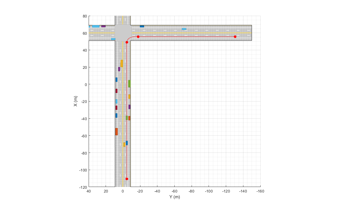
snapnow;
The local motion planning algorithm in this example consists of three main steps:
Sample local trajectories
Find feasible and collision-free trajectories
Choose optimality criterion and select optimal trajectory
The following sections discuss each step of the local planning algorithm and the helper functions used to execute each step.
Sample Local Trajectories
At each step of the simulation, the planning algorithm generates a list of sample trajectories that the ego vehicle can choose. The local trajectories are sampled by connecting the current state of the ego vehicle to desired terminal states. Use the trajectoryGeneratorFrenet (Navigation Toolbox) object to connect current and terminal states for generating local trajectories. Define the object by providing the reference path and the desired resolution in time for the trajectory. The object connects initial and final states in Frenet coordinates using fifth-order polynomials.
connector = trajectoryGeneratorFrenet(refPath,'TimeResolution',0.1);The strategy for sampling terminal states in Frenet coordinates often depends on the road network and the desired behavior of the ego vehicle during different phases of the global path. For more detailed examples of using different ego behavior, such as cruise-control and car-following, refer to the "Planning Adaptive Routes Through Traffic" section of the Highway Trajectory Planning Using Frenet Reference Path (Navigation Toolbox) example. In this example, you sample the terminal states using two different strategies, depending on the location of vehicle on the reference path, shown as blue and green regions in the following figure.
% Visualize path regions for sampling strategy visualization
pathPoints = closestPoint(refPath, refPath.Waypoints(:,1:2));
roadS = pathPoints(:,end);
intersectionS = roadS(2,end);
intersectionBuffer = 20;
pathGreen = [interpolate(refPath,linspace(0,intersectionS-intersectionBuffer,20));...
            nan(1,6);...
            interpolate(refPath,linspace(intersectionS,roadS(end),100))];
pathBlue = interpolate(refPath,linspace(intersectionS-intersectionBuffer,roadS(2,end),20));
hold(ax,'on');
plot(ax,pathGreen(:,1),pathGreen(:,2),'Color',[0 1 0],'LineWidth',5);
plot(ax,pathBlue(:,1),pathBlue(:,2),'Color',[0 0 1],'LineWidth',5);
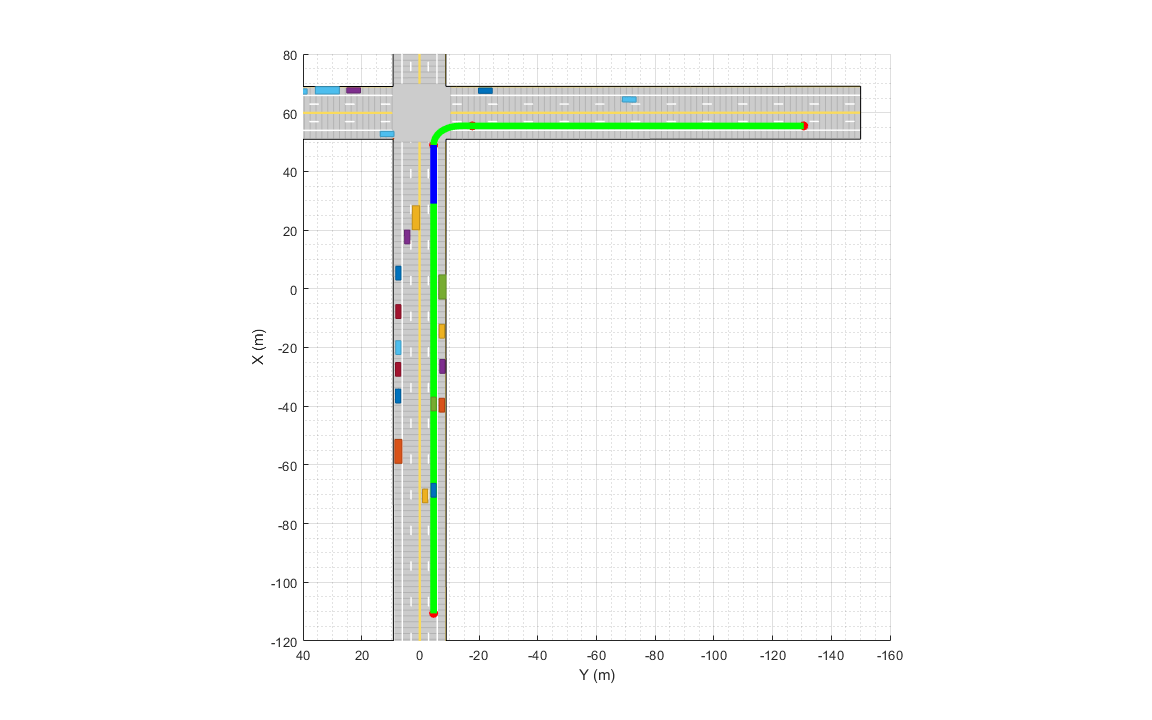
snapnow;
When the ego vehicle is in the green region, the following strategy is used to sample local trajectories. The terminal state of the ego vehicle after time is defined as:
where discrete samples for variables are obtained using the following predefined sets:
The use of NaN in the terminal state enables the trajectoryGeneratorFrenet object to automatically compute the longitudinal distance traveled over a minimum-jerk trajectory. This strategy produces a set of trajectories that enable the ego vehicle to accelerate up to the maximum speed limit () rates or decelerate to a full stop at different rates. In addition, the sampled choices of lateral offset () allow the ego vehicle to change lanes during these maneuvers.
% Define smax and wlane
speedLimit = 15;
laneWidth = 2.975;
When the ego vehicle is in the blue region of the trajectory, the following strategy is used to sample local trajectories:
;
where is chosen to minimize jerk during the trajectory. This strategy enables the vehicle to stop at the desired distance () in the right lane with a minimum-jerk trajectory. The trajectory sampling algorithm is wrapped inside the helper function, helperGenerateTrajectory, attached with this example.
Finding Feasible and Collision-Free Trajectories
The sampling process described in the previous section can produce trajectories that are kinematically infeasible and exceed thresholds of kinematic attributes such as acceleration and curvature. Therefore, you limit the maximum acceleration and speed of the ego vehicle using the helper function helperKinematicFeasibility, which checks the feasibility of each trajectory against these kinematic constraints.
% Define kinematic constraints
accMax = 15;
Further, you set up a collision-validator to assess if the ego vehicle can maneuver on a kinematically feasible trajectory without colliding with any other obstacles in the environment. To define the validator, use the helper class HelperDynamicMapValidator. This class uses the predictMapToTime (Sensor Fusion and Tracking Toolbox) function of the trackerGridRFS object to get short-term predictions of the occupancy of the surrounding environment. Since the uncertainty in the estimate increases with time, configure the validator with a maximum time horizon of 2 seconds.
The predicted occupancy of the environment is converted to an inflated costmap at each step to account for the size of the ego vehicle. The path planner uses a timestep of 0.1 seconds with a prediction time horizon of 2 seconds. To reduce computational complexity, the occupancy of the surrounding environment is assumed to be valid for 5 time steps, or 0.5 seconds. As a result, only 4 predictions are required in the 2-second planning horizon. In addition to making binary decisions about collision or no collision, the validator also provides a measure of collision probability of the ego vehicle. This probability can be incorporated into the cost function for optimality criteria to account for uncertainty in the system and to make better decisions without increasing the time horizon of the planner.
vehDims = vehicleDimensions(egoVehicle.Length,egoVehicle.Width);
collisionValidator = HelperDynamicMapValidator('MaxTimeHorizon',2, ... % Maximum horizon for validation
    'TimeResolution',connector.TimeResolution, ... % Time steps between trajectory samples
    'Tracker',tracker, ... % Provide tracker for prediction
    'ValidPredictionSpan',5, ... % Prediction valid for 5 steps
    'VehicleDimensions',vehDims); % Provide dimensions of ego
Choose Optimality Criterion
After validating the feasible trajectories against obstacles or occupied regions of the environment, choose an optimality criterion for each valid trajectory by defining a cost function for the trajectories. Different cost functions are expected to produce different behaviors from the ego vehicle. In this example, you define the cost of each trajectory as
where:
is the jerk in the longitudinal direction of the reference path
is the jerk in the lateral direction of the reference path
is the collision probability obtained by the validator
The cost calculation for each trajectory is defined using the helper function helperCalculateTrajectoryCosts. From the list of valid trajectories, the trajectory with the minimum cost is considered as the optimal trajectory.
Run Scenario, Estimate Dynamic Map, and Plan Local Trajectories
Run the scenario, generate point clouds from all the lidar sensors, and estimate the dynamic occupancy grid map. Use the dynamic map estimate and its predictions to plan a local trajectory for the ego vehicle.
% Close original figure and initialize a new display
close(fig);
display = helperGridBasedPlanningDisplay;

% Initial ego state
currentEgoState = [-110.6 -1.5 0 0 15 0];
helperMoveEgoVehicleToState(egoVehicle, currentEgoState);

% Initialize pointCloud outputs from each sensor
ptClouds = cell(numel(lidars),1);
sensorConfigs = cell(numel(lidars),1);

% Simulation Loop
while advance(scenario)
    % Current simulation time
    time = scenario.SimulationTime;

    % Poses of objects with respect to ego vehicle
    tgtPoses = targetPoses(egoVehicle);

    % Simulate point cloud from each sensor
    for i = 1:numel(lidars)
        [ptClouds{i}, isValidTime] = step(lidars{i},tgtPoses,time);
        sensorConfigs{i} = helperGetLidarConfig(lidars{i},egoVehicle);
    end

    % Pack point clouds as sensor data format required by the tracker
    sensorData = packAsSensorData(ptClouds,sensorConfigs,time);

    % Call the tracker
    [tracks, ~, ~, map] = tracker(sensorData,sensorConfigs,time);

    % Update validator's future predictions using current estimate
    step(collisionValidator, currentEgoState, map, time);

    % Sample trajectories using current ego state and some kinematic
    % parameters
    [frenetTrajectories, globalTrajectories] = helperGenerateTrajectory(connector, refPath, currentEgoState, speedLimit, laneWidth, intersectionS, intersectionBuffer);

    % Calculate kinematic feasibility of generated trajectories
    isKinematicsFeasible = helperKinematicFeasibility(frenetTrajectories,speedLimit,accMax);

    % Calculate collision validity of feasible trajectories
    feasibleGlobalTrajectories = globalTrajectories(isKinematicsFeasible);
    feasibleFrenetTrajectories = frenetTrajectories(isKinematicsFeasible);
    [isCollisionFree, collisionProb] = isTrajectoryValid(collisionValidator, feasibleGlobalTrajectories);

    % Calculate costs and final optimal trajectory
    nonCollidingGlobalTrajectories = feasibleGlobalTrajectories(isCollisionFree);
    nonCollidingFrenetTrajectories = feasibleFrenetTrajectories(isCollisionFree);
    nonCollodingCollisionProb = collisionProb(isCollisionFree);
    costs = helperCalculateTrajectoryCosts(nonCollidingFrenetTrajectories, nonCollodingCollisionProb, speedLimit);

    % Find optimal trajectory
    [~,idx] = min(costs);
    optimalTrajectory = nonCollidingGlobalTrajectories(idx);

    % Assemble for plotting
    trajectories = helperAssembleTrajectoryForPlotting(globalTrajectories, ...
        isKinematicsFeasible, isCollisionFree, idx);

    % Update display
    display(scenario, egoVehicle, lidars, ptClouds, tracker, tracks, trajectories, collisionValidator);

    % Move ego with optimal trajectory
    if ~isempty(optimalTrajectory)
        currentEgoState = optimalTrajectory.Trajectory(2,:);
        helperMoveEgoVehicleToState(egoVehicle, currentEgoState);
    else
        % All trajectories either violated kinematic feasibility
        % constraints or resulted in a collision. More behaviors on
        % trajectory sampling may be needed.
        error('Unable to compute optimal trajectory');
    end
end
Results
Analyze the results from the local path planning algorithm and how the predictions from the map assisted the planner. This animation shows the result of the planning algorithm during the entire scenario. Notice that the ego vehicle successfully reached its desired destination and maneuvered around different dynamic objects, whenever necessary. The ego vehicle also came to a stop at the intersection due to the regional changes added to the sampling policy.

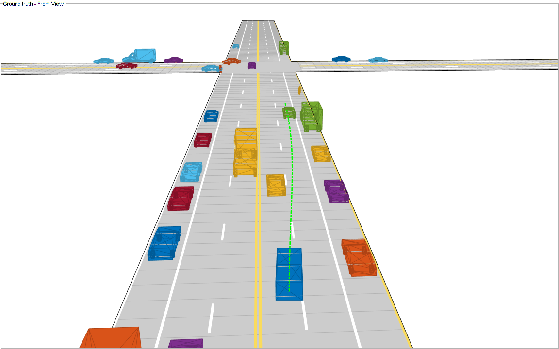
Next, analyze the local planning algorithm during the first lane change. The snapshots in this section are captured at time = 4.3 seconds during the simulation.
In this snapshot, the ego vehicle has just started to perform a lane change maneuver into the right lane.
showSnaps(display, 3, 1);
The snapshot that follows shows the estimate of the dynamic grid at the same time step. The color of the grid cell denotes the direction of motion of the object occupying that grid cell. Notice that the cells representing the car in front of the ego vehicle are colored red, denoting that the cells are occupied with a dynamic object. Also, the car is moving in the positive X direction of the scenario, so based on the color wheel, the color of the corresponding grid cells is red.
f = showSnaps(display, 2, 1);
if ~isempty(f)
    ax = findall(f,'Type','Axes');
    ax.XLim = [0 40];
    ax.YLim = [-20 20];
    s = findall(ax,'Type','Surf');
    s.XData = 36 + 1/3*(s.XData - mean(s.XData(:)));
    s.YData = 16 + 1/3*(s.YData - mean(s.YData(:)));
end

Based on the previous image, the planned trajectory of the ego vehicle passes through the occupied regions of space, representing a collision if you performed a traditional static occupancy validation. The dynamic occupancy map and the validator, however, account for the dynamic nature of the grid by validating the state of the trajectory against the predicted occupancy at each time step. The next snapshot shows the predicted costmap at different prediction steps (), along with the planned position of the ego vehicle on the trajectory. The predicted costmap is inflated to account for size of the ego vehicle. Therefore, if a point object representing the origin of the ego vehicle can be placed on the occupancy map without any collision, it can be interpreted that the ego vehicle does not collide with any obstacle. The yellow regions on the costmap denote areas with guaranteed collisions with an obstacle. The collision probability decays outside the yellow regions exponentially until the end of inflation region. The blue regions indicate areas with zero probability of collision according to the current prediction.
Notice that the yellow region representing the car in front of the ego vehicle moves forward on the costmap as the map is predicted in the future. This reflects that the prediction of occupancy considers the velocity of objects in the surrounding environment. Also, notice that the cells classified as static objects remained relatively static on the grid during the prediction. Lastly, notice that the planned position of the ego vehicle origin does not collide with any occupied regions in the cost map. This shows that the ego vehicle can successfully maneuver on this trajectory.
f = showSnaps(display, 1, 1);
if ~isempty(f)
ax = findall(f,'Type','Axes');
for i = 1:numel(ax)
    ax(i).XLim = [0 40];
    ax(i).YLim = [-20 20];
end
end

Summary
In this example, you learned how to use the dynamic map predictions from the grid-based tracker, trackerGridRFS, and how to integrate the dynamic map with a local path planning algorithm to generate trajectories for the ego vehicle in dynamic complex environments. You also learned how the dynamic nature of the occupancy can be used to plan trajectories more efficiently in the environment.
Supporting Functions
function sensorData = packAsSensorData(ptCloud, configs, time)
% Pack the sensor data as format required by the tracker
%
% ptCloud - cell array of pointCloud object
% configs - cell array of sensor configurations
% time    - Current simulation time

%The lidar simulation returns outputs as pointCloud objects. The Location
%property of the point cloud is used to extract x,y, and z locations of
%returns and pack them as structures with information required by a tracker.
sensorData = struct('SensorIndex',{},...
    'Time', {},...
    'Measurement', {},...
    'MeasurementParameters', {});

for i = 1:numel(ptCloud)
    % This sensor's point cloud
    thisPtCloud = ptCloud{i};

    % Allows mapping between data and configurations without forcing an
    % ordered input and requiring configuration input for static sensors.
    sensorData(i).SensorIndex = configs{i}.SensorIndex;

    % Current time
    sensorData(i).Time = time;

    % Exctract Measurement as a 3-by-N defining locations of points
    sensorData(i).Measurement = reshape(thisPtCloud.Location,[],3)';

    % Data is reported in the sensor coordinate frame and hence measurement
    % parameters are same as sensor transform parameters.
    sensorData(i).MeasurementParameters = configs{i}.SensorTransformParameters;
end

end

function config = helperGetLidarConfig(lidar, ego)
% Get configuration of the lidar sensor for tracker
%
% config - Configuration of the lidar sensor in the world frame
% lidar - lidarPointCloudGeneration object
% ego   - driving.scenario.Actor in the scenario

% Define transformation from sensor to ego
senToEgo = struct('Frame',fusionCoordinateFrameType(1),...
    'OriginPosition',[lidar.SensorLocation(:);lidar.Height],...
    'Orientation',rotmat(quaternion([lidar.Yaw lidar.Pitch lidar.Roll],'eulerd','ZYX','frame'),'frame'),...
    'IsParentToChild',true);

% Define transformation from ego to tracking coordinates
egoToScenario = struct('Frame',fusionCoordinateFrameType(1),...
    'OriginPosition',ego.Position(:),...
    'Orientation',rotmat(quaternion([ego.Yaw ego.Pitch ego.Roll],'eulerd','ZYX','frame'),'frame'),...
    'IsParentToChild',true);

% Assemble using trackingSensorConfiguration.
config = trackingSensorConfiguration(...
    'SensorIndex',lidar.SensorIndex,...
    'IsValidTime', true,...
    'SensorLimits',[lidar.AzimuthLimits;0 lidar.MaxRange],...
    'SensorTransformParameters',[senToEgo;egoToScenario],...
    'DetectionProbability',0.95);

end

function helperMoveEgoVehicleToState(egoVehicle, currentEgoState)
% Move ego vehicle in scenario to a state calculated by the planner
%
% egoVehicle - driving.scenario.Actor in the scenario
% currentEgoState - [x y theta kappa speed acc]

% Set 2-D Position
egoVehicle.Position(1:2) = currentEgoState(1:2);

% Set 2-D Velocity (s*cos(yaw) s*sin(yaw))
egoVehicle.Velocity(1:2) = [cos(currentEgoState(3)) sin(currentEgoState(3))]*currentEgoState(5);

% Set Yaw in degrees
egoVehicle.Yaw = currentEgoState(3)*180/pi;

% Set angular velocity in Z (yaw rate) as v/r
egoVehicle.AngularVelocity(3) = currentEgoState(4)*currentEgoState(5);

end

function isFeasible = helperKinematicFeasibility(frenetTrajectories, speedLimit, aMax)
% Check kinematic feasibility of trajectories
%
% frenetTrajectories - Array of trajectories in Frenet coordinates
% speedLimit - Speed limit (m/s)
% aMax - Maximum acceleration (m/s^2)

isFeasible = false(numel(frenetTrajectories),1);
for i = 1:numel(frenetTrajectories)
    % Speed of the trajectory
    speed = frenetTrajectories(i).Trajectory(:,2);

    % Acceleration of the trajectory
    acc = frenetTrajectories(i).Trajectory(:,3);

    % Is speed valid?
    isSpeedValid = ~any(speed < -0.1 | speed > speedLimit + 1);

    % Is acceleration valid?
    isAccelerationValid = ~any(abs(acc) > aMax);

    % Trajectory feasible if both speed and acc valid
    isFeasible(i) = isSpeedValid & isAccelerationValid;
end

end

function cost = helperCalculateTrajectoryCosts(frenetTrajectories, Pc, smax)
% Calculate cost for each trajectory.
%
% frenetTrajectories - Array of trajectories in Frenet coordinates
% Pc - Probability of collision for each trajectory calculated by validator

n = numel(frenetTrajectories);
Jd = zeros(n,1);
Js = zeros(n,1);
s = zeros(n,1);

for i = 1:n
    % Time
    time = frenetTrajectories(i).Times;

    % resolution
    dT = time(2) - time(1);

    % Jerk along the path
    dds = frenetTrajectories(i).Trajectory(:,3);
    Js(i) = sum(gradient(dds,time).^2)*dT;

    % Jerk perpendicular to path
    % d2L/dt2 = d/dt(dL/ds*ds/dt)
    ds = frenetTrajectories(i).Trajectory(:,2);
    ddL = frenetTrajectories(i).Trajectory(:,6).*(ds.^2) + frenetTrajectories(i).Trajectory(:,5).*dds;
    Jd(i) = sum(gradient(ddL,time).^2)*dT;

    s(i) = frenetTrajectories(i).Trajectory(end,2);
end

cost = Js + Jd + 1000*Pc(:) + 100*(s - smax).^2;

end