モデル コンポーネントの剛体アセンブリ
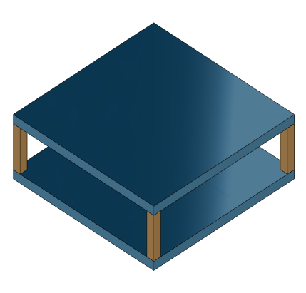
この例では、構造モデルのコンポーネント間に剛体の物理結合を指定する方法を説明します。下の図に示すように、各頂点で支柱に連結された 2 枚の正方形のプレートで構成される構造について考えます。下部のプレートは地面に剛結合されていますが、支柱は正方形のプレートの各頂点に剛結合されています。
スパース モデルの詳細については、スパース モデルの基礎を参照してください。
platePillarModel.mat には支柱とプレートのモデルのスパース行列が含まれています。platePillarModel.mat に含まれている有限要素モデル行列を読み込み、上記システムを表すスパース 2 次状態空間モデルを作成します。
load('platePillarModel.mat')
Plate1 = mechss(M1,[],K1,B1,F1,'Name','Plate1');
Plate2 = mechss(M2,[],K2,B2,F2,'Name','Plate2');
次に、相互作用する DOF インデックス データを dofData.mat から読み込み、addInterfaceを使用して 2 枚のプレートと 4 本の支柱間の接続用の結合インターフェイスを作成します。dofs は、最初の 2 つの行に 1 枚目と 2 枚目のプレートの DOF インデックス データを含み、他の 4 つの行に 4 本の支柱のインデックス データを含む 6x7 cell 配列です。
load('dofData.mat','dofs')
プレートから支柱へのインターフェイスを定義します。
for ct=1:4
    Plate1 = addInterface(Plate1,"Pillar"+ct,dofs{1,2+ct});
    Plate2 = addInterface(Plate2,"Pillar"+ct,dofs{2,2+ct});
end
支柱からプレートへのインターフェイスを定義します。
P = cell(4,1);
for ct=1:4
    P{ct} = mechss(Mp,[],Kp,Bp,Fp,'Name',"Pillar"+ct);
    P{ct} = addInterface(P{ct},"TopMount",dofs{2+ct,1});
    P{ct} = addInterface(P{ct},"BottomMount",dofs{2+ct,2});
end
Plate2 から地面へのインターフェイスを定義します。
Plate2 = addInterface(Plate2,"Ground",dofs{2,7});結果のモデル sys は 5820 自由度、1 つの入力と 1 つの出力をもちます。mechss モデル オブジェクトのコンポーネントを確認するには showStateInfo を使用します。
sys = append(Plate1,Plate2,P{:})Sparse continuous-time second-order model with 204 outputs, 204 inputs, and 5820 degrees of freedom. Model Properties Use "spy" and "showStateInfo" to inspect model structure. Type "help mechssOptions" for available solver options for this model.
showStateInfo(sys)
The state groups are:

    Type        Name      Size
  ----------------------------
  Component    Plate1     2646
  Component    Plate2     2646
  Component    Pillar1     132
  Component    Pillar2     132
  Component    Pillar3     132
  Component    Pillar4     132
名前のあるコンポーネントがそれぞれのサイズとともに出力にリストされます。
今度は、プレートと支柱間の剛結合を指定します。
sysCon = sys;
for ct=1:4
    sysCon = assemble(sysCon,"Plate1:Pillar"+ct,"Pillar"+ct+":TopMount"');
    sysCon = assemble(sysCon,"Plate2:Pillar"+ct,"Pillar"+ct+":BottomMount");
end
下部プレートと地面との間の剛結合を指定します。
sysCon = assemble(sysCon,"Plate2:Ground","Ground")
Sparse continuous-time second-order model with 6 outputs, 6 inputs, and 5922 degrees of freedom.
Model Properties

Use "spy" and "showStateInfo" to inspect model structure.
Type "help mechssOptions" for available solver options for this model.
これで、モデルに 5922 自由度が含まれるようになったことに注意してください。追加の DOF は特定の剛体のインターフェイスによる結果です。
assembleは 'デュアル アセンブリ' の定式化を使用してコンポーネントに接続します。デュアル アセンブリの概念では、自由度 (DoF) のグローバル セット が維持され、物理結合は、インターフェイスにおける整合性と平衡拘束として表されます。剛結合の場合、これらの制約は次の形式になります。
ここで はインターフェイスにおける内力のベクトルであり、行列 は に並べ替えることができます。インデックス 、 をもつ一致する DOF のペアの場合、 は最初のコンポーネントで DOF を選択する一方、 は 2 番目のコンポーネントで一致する DOF を選択し、 は変位の一貫性を強制します。
一方、 はインターフェイスで内力 の平衡を強制します。
.
これらの制約を分離された方程式 と組み合わせると、連結システムに対して次のデュアル アセンブリ モデルが導かれます。
showStateInfo を使用して物理接続を確認します。
showStateInfo(sysCon)
The state groups are:

    Type                      Name                   Size
  -------------------------------------------------------
  Component                  Plate1                  2646
  Component                  Plate2                  2646
  Component                 Pillar1                   132
  Component                 Pillar2                   132
  Component                 Pillar3                   132
  Component                 Pillar4                   132
  Interface     Plate1:Pillar1-Pillar1:TopMount        12
  Interface    Plate2:Pillar1-Pillar1:BottomMount      12
  Interface     Plate1:Pillar2-Pillar2:TopMount        12
  Interface    Plate2:Pillar2-Pillar2:BottomMount      12
  Interface     Plate1:Pillar3-Pillar3:TopMount        12
  Interface    Plate2:Pillar3-Pillar3:BottomMount      12
  Interface     Plate1:Pillar4-Pillar4:TopMount        12
  Interface    Plate2:Pillar4-Pillar4:BottomMount      12
  Interface           Plate2:Ground-Ground              6
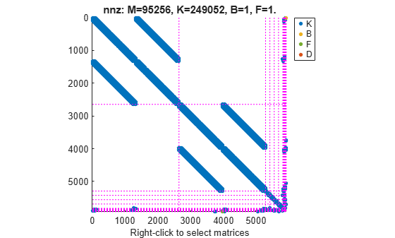
spyを使用して、最終モデルのスパース行列を可視化できます。プロットを右クリックしてアクセスできる [表示] メニューを使用して、表示する行列を選択します。
spy(sysCon)
謝辞
この例のデータセットは、ASML の Victor Dolk によって提供されています。
参考
addInterface | assemble | xsort | showStateInfo | spy | mechss