パルス整形とフィルター処理を使用する場合の変調の例
矩形パルス整形
矩形パルス整形は、変調器からの各出力を固定した回数繰り返して、アップサンプリングされた信号を作成します。矩形パルス整形は、他の種類のパルス整形よりも実際的ではありませんが、アルゴリズム開発で、最初のステップあるいは予備的なステップになることがあります。送信側が変調信号をアップサンプリングしている場合、受信側は復調前に受信信号をダウンサンプリングする必要があります。以下のコードは、送信機の矩形パルス整形に関数rectpulseを使用し、受信機のダウンサンプリングに関数intdumpを使用します。積分とダンプの操作は、受信した信号をダウンサンプリングする方法の 1 つです。
シミュレーション変数を定義し、ランダムなデジタル メッセージを作成します。
M = 16;                     % Alphabet size, 16-QAM
Nsamp = 4;                  % Oversampling rate
snr = 15;                   % Signal to noise ratio in dB
x = randi([0 M-1],5000,1);  % Message signal
16-QAM 変調と矩形パルス整形を適用します。AWGN チャネルを通して信号を送信します。
y = qammod(x,M);
ypulse = rectpulse(y,Nsamp);
ynoisy = awgn(ypulse,15,'measured');受信機でダウンサンプリングします。spectrumAnalyzerを使用して、パルス整形された送信信号を AWGN 付加の前と後で比較します。
ydownsamp = intdump(ynoisy,Nsamp);
sa1 = spectrumAnalyzer( ...
    Title="16-QAM Signal with Rectangular Pulse Shaping", ...
    ChannelNames={'No noise','SNR=15 dB'});
sa1(ypulse,ynoisy)

メッセージを復元するために復調します。
z = qamdemod(ydownsamp,M);
レイズド コサイン フィルター System object を使ったパルス整形
対になるルート レイズド コサイン整合フィルター処理を使用して 16-QAM 信号のフィルター処理を行います。信号のアイ ダイアグラムおよび散布図をプロットします。AWGN チャネル経由で信号を渡した後にビット エラー数を計算します。
シミュレーションとフィルターのパラメーターを設定します。
M = 16;         % Modulation order
bps = log2(M);  % Bits per symbol
n = 20000;      % Transmitted bits
sps = 4;        % Samples per symbol
EbNo = 10;      % Eb/N0 (dB)
span = 10;      % Filter span in symbols
rolloff = 0.25; % Filter rolloff factor
定義したパラメーターを使用して、レイズド コサイン送信フィルター オブジェクトおよびレイズド コサイン受信フィルター オブジェクトを作成します。
txfilter = comm.RaisedCosineTransmitFilter( ...
    RolloffFactor=rolloff, ...
    FilterSpanInSymbols=span, ...
    OutputSamplesPerSymbol=sps);

rxfilter = comm.RaisedCosineReceiveFilter( ...
    RolloffFactor=rolloff, ...
    FilterSpanInSymbols=span, ...
    InputSamplesPerSymbol=sps, ...
    DecimationFactor=sps);
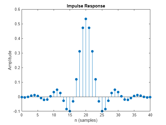
レイズド コサイン送信フィルター オブジェクト txFilter のインパルス応答をプロットします。
impz(txfilter.coeffs.Numerator)
整合フィルターによる遅延を計算します。群遅延は、1 つのフィルター全体のフィルター スパンの半分であるため、両方のフィルターのフィルター スパンと等しくなります。シンボルあたりのビット数を掛けてビット単位の遅延を取得します。
filtDelay = bps*span;
エラー レート カウンター System object™ を作成します。ReceiveDelay プロパティを設定して整合フィルターによる遅延が考慮されるようにします。
errorRate = comm.ErrorRate(ReceiveDelay=filtDelay);
バイナリ データを生成します。
x = randi([0 1],n,1);
データを変調します。
modSig = qammod(x,M,InputType="bit");変調された信号をフィルター処理し、先頭から 1000 個のサンプルのアイ ダイアグラムをプロットします。
txSig = txfilter(modSig);
eyediagram(txSig(1:1000),sps)

を指定して S/N 比 (SNR) を dB 単位で計算します。関数 awgn を使用して AWGN チャネル経由で送信信号を渡します。
SNR = convertSNR(EbNo,"ebno","snr", ...
    SamplesPerSymbol=sps, ...
    BitsPerSymbol=bps);
noisySig = awgn(txSig,SNR,"measured");
ノイズを含む信号をフィルター処理し、アイ ダイアグラムと散布図を表示します。
rxSig = rxfilter(noisySig);
eyediagram(rxSig(1:1000),sps)

scatterplot(rxSig)

フィルター処理された信号を復調し、誤り統計を計算します。フィルターによる遅延は、errorRate の ReceiveDelay プロパティによって考慮されています。
z = qamdemod(rxSig,M,OutputType="bit");

errStat = errorRate(x,z);
fprintf('\nBER = %5.2e\nBit Errors = %d\nBits Transmitted = %d\n',...
    errStat)
BER = 1.15e-03
Bit Errors = 23
Bits Transmitted = 19960
nzmod = awgn(modSig,SNR,"measured");
demodsig = qamdemod(nzmod,M,OutputType="bit");
errorRate2 = comm.ErrorRate;
errStat2 = errorRate2(x,demodsig);
fprintf('\nBER = %5.2e\nBit Errors = %d\nBits Transmitted = %d\n',...
    errStat2)
BER = 5.86e-02
Bit Errors = 1172
Bits Transmitted = 20000