NR PUSCH スループット
この参照シミュレーションでは、3GPP NR 規格で定義されているように、5G New Radio (NR) リンクの物理アップリンク共有チャネル (PUSCH) のスループットを測定する方法を示します。この例では、PUSCH とアップリンク トランスポート チャネル (UL-SCH) を実装します。送信機モデルには、PUSCH 復調基準信号 (DM-RS) が含まれます。この例では、クラスター遅延線 (CDL) とタップ付き遅延線 (TDL) の両方の伝播チャネルをサポートします。完全な同期と完全なチャネル推定、あるいは実用的な同期と実用的なチャネル推定を実行できます。シミュレーションの合計時間を短縮するために、Parallel Computing Toolbox™ を使用して、SNR ループの SNR 点を並列に処理できます。
はじめに
この例では、3GPP NR 規格 [ 1 ]、[ 2 ]、[ 3 ]、[ 4 ] で定義されているように、5G リンクの PUSCH スループットを測定します。
この例では、次の 5G NR の機能をモデル化します。
UL-SCH トランスポート チャネル符号化
PUSCH と PUSCH DM-RS の生成
可変サブキャリア間隔とフレーム numerology (2^n * 15 kHz)
ノーマル サイクリック プレフィックスと拡張サイクリック プレフィックス
TDL と CDL の伝播チャネル モデル
シミュレーションのその他の機能は、次のとおりです。
コードブック ベースおよび非コードブック ベースの PUSCH トランスミッション スキーム
オプションの PUSCH トランスフォーム プリコーディング
スロット単位および非スロット単位での PUSCH と DM-RS のマッピング
完全な同期と完全なチャネル推定、あるいは実用的な同期と実用的なチャネル推定
16 個のプロセスを使用する HARQ 操作
次の図は、実装される処理チェーンを示しています。わかりやすくするために、DM-RS の生成は省略しています。

この例には、チャネル条件に応じた MIMO プリコーディングの閉ループ適用が含まれていないことに注意してください。この例で使用する PUSCH MIMO プリコーディングは以下のとおりです。
コードブック ベースの送信の場合、PUSCH 変調の内部で使用される MIMO プリコーディング行列は、TPMI パラメーターを使用して選択できる。
実装固有の MIMO プリコーディング行列 (非コードブック ベースの送信の場合、またはコードブック ベースの送信で送信アンテナ ポートとアンテナの間で MIMO プリコーディングを行う場合) は、単位行列になる。
シミュレーションの合計を短縮するために、Parallel Computing Toolbox を使用して、SNR ループの SNR 点を並列に処理できます。
シミュレーションの長さと SNR 点
シミュレーションの長さを 10 ms のフレームの数で設定します。有意なスループットの結果を得るためには、多数の NFrame を使用する必要があります。シミュレーションを行うための SNR 点を設定します。SNR は RE ごとに定義され、それぞれの受信アンテナに適用されます。この例で使用している SNR 定義の説明については、リンク シミュレーションで使用する SNR の定義を参照してください。
simParameters = struct();       % Clear simParameters variable to contain all key simulation parameters
simParameters.NFrames = 2;      % Number of 10 ms frames
simParameters.SNRIn = [-5 0 5]; % SNR range (dB)
チャネル推定器の構成
logical 変数 PerfectChannelEstimator は、チャネル推定と同期の動作を制御します。true に設定すると、完全なチャネル推定と同期が使用されます。それ以外の場合、受信した PUSCH DM-RS の値に基づいて、実用的なチャネル推定と同期が使用されます。
simParameters.PerfectChannelEstimator = true;
シミュレーション診断
変数 DisplaySimulationInformation は、各サブフレームに使用される HARQ プロセス ID などのシミュレーション情報の表示を制御します。CRC エラーの場合、RV シーケンスへのインデックスの値も表示されます。
simParameters.DisplaySimulationInformation = true;
DisplayDiagnostics フラグは、レイヤーごとの EVM のプロットを有効にします。このプロットは、イコライズ後の受信信号の品質を監視します。レイヤーごとの EVM の Figure は以下を表示します。
スロット単位でのレイヤーごとの EVM。これは時間とともに変化する EVM を表示します。
リソース ブロック単位でのレイヤーごとの EVM。これは EVM の周波数を示します。
この Figure はシミュレーションとともに変化し、スロットごとに更新されます。通常、低い SNR またはチャネル フェージングは、信号品質の低下 (高 EVM) につながる可能性があります。チャネルは各レイヤーに異なる影響を与えるため、EVM 値はレイヤー間で異なる場合があります。
場合によっては、一部のレイヤーの EVM が他のレイヤーよりもはるかに高くなることがあります。そのような低品質のレイヤーは、CRC エラーを引き起こす可能性があります。この動作は、SNR が低いか、チャネル条件に対して使用するレイヤーが多すぎることが原因である可能性があります。この状況は、SNR を高くし、レイヤー数を減らし、アンテナ数を増やし、送信の堅牢性を高める (変調スキームとターゲット符号化率を低くする) ことを組み合わせることで回避できます。
simParameters.DisplayDiagnostics = false;
キャリアと PUSCH の構成
シミュレーションの主なパラメーターを設定します。これには、次が含まれます。
リソース ブロックの帯域幅 (リソース ブロックごとに 12 個のサブキャリア)
サブキャリア間隔: 15、30、60、120 (kHz)
サイクリック プレフィックス長: normal または extended
セル ID
送信アンテナ数と受信アンテナ数
UL-SCH と PUSCH のパラメーターを含むサブ構造体も指定します。これには、次が含まれます。
ターゲット符号化率
割り当て済みリソース ブロック数 (PRBSet)
変調スキーム: 'pi/2-BPSK'、'QPSK'、'16QAM'、'64QAM'、'256QAM'
レイヤーの数
トランスフォーム プリコーディング (有効/無効)
PUSCH トランスミッション スキームと MIMO のプリコーディング行列指標 (TPMI)
アンテナ ポート数
PUSCH マッピング タイプ
DM-RS 構成パラメーター
PT-RS 構成パラメーター
その他のシミュレーション全体のパラメーターは、次のとおりです。
伝播チャネル モデル遅延プロファイル (TDL または CDL)
トランスフォーム プリコーディングが有効な場合は、レイヤーの数を 1 に設定する必要があることに注意してください。
% Set waveform type and PUSCH numerology (SCS and CP type)
simParameters.Carrier = nrCarrierConfig;        % Carrier resource grid configuration
simParameters.Carrier.NSizeGrid = 52;           % Bandwidth in number of resource blocks (52 RBs at 15 kHz SCS for 10 MHz BW)
simParameters.Carrier.SubcarrierSpacing = 15;   % 15, 30, 60, 120 (kHz)
simParameters.Carrier.CyclicPrefix = 'Normal';  % 'Normal' or 'Extended' (Extended CP is relevant for 60 kHz SCS only)
simParameters.Carrier.NCellID = 0;              % Cell identity

% PUSCH/UL-SCH parameters
simParameters.PUSCH = nrPUSCHConfig;      % This PUSCH definition is the basis for all PUSCH transmissions in the BLER simulation
simParameters.PUSCHExtension = struct();  % This structure is to hold additional simulation parameters for the UL-SCH and PUSCH

% Define PUSCH time-frequency resource allocation per slot to be full grid (single full grid BWP)
simParameters.PUSCH.PRBSet =  0:simParameters.Carrier.NSizeGrid-1; % PUSCH PRB allocation
simParameters.PUSCH.SymbolAllocation = [0,simParameters.Carrier.SymbolsPerSlot]; % PUSCH symbol allocation in each slot
simParameters.PUSCH.MappingType = 'A'; % PUSCH mapping type ('A'(slot-wise),'B'(non slot-wise))

% Scrambling identifiers
simParameters.PUSCH.NID = simParameters.Carrier.NCellID;
simParameters.PUSCH.RNTI = 1;

% Define the transform precoding enabling, layering and transmission scheme
simParameters.PUSCH.TransformPrecoding = false; % Enable or disable transform precoding
simParameters.PUSCH.NumLayers = 1;              % Number of PUSCH transmission layers
simParameters.PUSCH.TransmissionScheme = 'nonCodebook'; % Transmission scheme ('nonCodebook','codebook')
simParameters.PUSCH.NumAntennaPorts = 1;        % Number of antenna ports for codebook based precoding
simParameters.PUSCH.TPMI = 0;                   % Precoding matrix indicator for codebook based precoding

% Define codeword modulation
simParameters.PUSCH.Modulation = 'QPSK'; % 'pi/2-BPSK', 'QPSK', '16QAM', '64QAM', '256QAM'

% PUSCH DM-RS configuration
simParameters.PUSCH.DMRS.DMRSTypeAPosition = 2;       % Mapping type A only. First DM-RS symbol position (2,3)
simParameters.PUSCH.DMRS.DMRSLength = 1;              % Number of front-loaded DM-RS symbols (1(single symbol),2(double symbol))
simParameters.PUSCH.DMRS.DMRSAdditionalPosition = 1;  % Additional DM-RS symbol positions (max range 0...3)
simParameters.PUSCH.DMRS.DMRSConfigurationType = 1;   % DM-RS configuration type (1,2)
simParameters.PUSCH.DMRS.NumCDMGroupsWithoutData = 2; % Number of CDM groups without data
simParameters.PUSCH.DMRS.NIDNSCID = 0;                % Scrambling identity (0...65535)
simParameters.PUSCH.DMRS.NSCID = 0;                   % Scrambling initialization (0,1)
simParameters.PUSCH.DMRS.NRSID = 0;                   % Scrambling ID for low-PAPR sequences (0...1007)
simParameters.PUSCH.DMRS.GroupHopping = 0;            % Group hopping (0,1)
simParameters.PUSCH.DMRS.SequenceHopping = 0;         % Sequence hopping (0,1)
simParameters.PUSCH.DMRS.DMRSPortSet = [];            % Use this to specify explicit DM-RS port numbers (TS 38.212 Section 7.3.1.1). Empty corresponds to the first NumLayers valid ports

% PUSCH PT-RS configuration
simParameters.PUSCH.EnablePTRS = false;               % Enable or disable PT-RS
simParameters.PUSCH.PTRS.TimeDensity = 1;             % PT-RS time density (L_PT-RS) (1, 2, 4)
simParameters.PUSCH.PTRS.FrequencyDensity = 2;        % PT-RS frequency density (K_PT-RS) (2, 4)
simParameters.PUSCH.PTRS.REOffset = '00';             % PT-RS resource element offset ('00', '01', '10', '11')
simParameters.PUSCH.PTRS.PTRSPortSet = [];            % PT-RS antenna port, subset of DM-RS port set. Empty corresponds to lower DM-RS port number

% Additional simulation and UL-SCH related parameters
%
% Target code rate
simParameters.PUSCHExtension.TargetCodeRate = 193 / 1024; % Code rate used to calculate transport block size
%
% HARQ process and rate matching/TBS parameters
simParameters.PUSCHExtension.XOverhead = 6*simParameters.PUSCH.EnablePTRS; % Set PUSCH rate matching overhead for TBS (Xoh) to 6 when PT-RS is enabled, otherwise 0
simParameters.PUSCHExtension.NHARQProcesses = 16; % Number of parallel HARQ processes to use
simParameters.PUSCHExtension.EnableHARQ = true;   % Enable retransmissions for each process, using RV sequence [0,2,3,1]
simParameters.PUSCHExtension.EnableCBGTransmission = false; % Enable CBG-based transmission, otherwise TB-based transmission
simParameters.PUSCHExtension.MaxNumCBG = 4;       % Maximum number of CBGs per transport block for each HARQ process in CBG-based transmission

% LDPC decoder parameters
% Available algorithms: 'Belief propagation', 'Layered belief propagation', 'Normalized min-sum', 'Offset min-sum'
simParameters.PUSCHExtension.LDPCDecodingAlgorithm = 'Normalized min-sum';
simParameters.PUSCHExtension.MaximumLDPCIterationCount = 6;

% Define the overall transmission antenna geometry at end-points
% If using a CDL propagation channel then the integer number of antenna elements is
% turned into an antenna panel configured when the channel model object is created
simParameters.NTxAnts = 1; % Number of transmit antennas
simParameters.NRxAnts = 2; % Number of receive antennas

% Define the general CDL or TDL propagation channel parameters.
% If you later want to debug unexpected simulation results, set DelayProfile to
% 'None' to disable channel impairments due to mobility, fading, multipath,
% delay, and antenna effects.
simParameters.DelayProfile = 'TDL-A'; % 'TDL-A', ..., 'TDL-E', 'CDL-A', ..., 'CDL-E', 'None'
simParameters.DelaySpread = 30e-9;
simParameters.MaximumDopplerShift = 10;

% Cross-check the PUSCH layering against the channel geometry
validateNumLayers(simParameters);
このシミュレーションは、サンプル レートなどのベースバンド波形に関するさまざまな情報に依存しています。
waveformInfo = nrOFDMInfo(simParameters.Carrier); % Get information about the baseband waveform after OFDM modulation step
伝播チャネル モデルの構築
シミュレーション用のチャネル モデル オブジェクトを作成します。CDL と TDL の両方のチャネル モデルをサポートします [ 5 ]。
[channel,simParameters] = createChannel(simParameters,waveformInfo);
最大チャネル遅延を取得します。
chInfo = info(channel);
maxChDelay = chInfo.MaximumChannelDelay;
処理ループ
各 SNR 点でのスループットを測定するために、以下の手順に従って、送信インスタンスごとの PUSCH データを解析します。
現在の HARQ プロセスの更新。提供された HARQ プロセスの送信ステータスをチェックし、再送が必要かどうかを決定します。そうでない場合は、新しいデータを生成します。
リソース グリッドの生成。
nrULSCHSystem object™ を使用して、チャネル符号化を実行します。このオブジェクトは、入力のトランスポート ブロックに対して動作し、再送が必要な場合はトランスポート ブロックの内部コピーを保持します。nrPUSCH関数を使用して、PUSCH の符号化ビットを変調します。次に、結果として得られた信号に実装固有の MIMO プリコーディングを適用します。TxScheme='codebook'の場合、nrPUSCHは内部でコードブックベースの MIMO プリコーディングを既に適用しているため、実装固有の MIMO プリコーディングは MIMO プリコーディングの追加の段階となることに注意してください。波形の生成。生成されたグリッドを OFDM 変調します。
ノイズを含むチャネルのモデル化。CDL または TDL のフェージング チャネルに波形を渡します。AWGN を付加します。この例で使用している SNR 定義の説明については、リンク シミュレーションで使用する SNR の定義を参照してください。
同期と OFDM 復調の実行。完全な同期では、チャネル インパルス応答を再構築して受信波形を同期させます。実用的な同期では、受信波形と PUSCH DM-RS の相関をとります。次に、同期した信号を OFDM 復調します。
チャネル推定の実行。完全なチャネル推定では、チャネル インパルス応答を再構築して OFDM 復調を実行します。実用的なチャネル推定では、PUSCH DM-RS を使用します。
イコライズと共通位相誤差 (CPE) 補償の実行。
nrEqualizeMMSE関数を使用して、チャネルを MMSE イコライズします。PT-RS シンボルを使用して CPE を推定した後、PT-RS OFDM 基準シンボルの範囲内にある各 OFDM シンボルの誤差を補正します。PUSCH の復号化。受信コードワードの推定を取得するために、
nrPUSCHDecode関数を使用して、送信アンテナと受信アンテナのすべてのペアについて復元した PUSCH シンボルを、ノイズ推定とともに復調し、デスクランブルします。アップリンク共有チャネル (UL-SCH) の復号化およびブロック CRC エラーのある HARQ プロセスの更新。復号化されたソフト ビットのベクトルを
nrULSCHDecoderSystem object に渡します。このオブジェクトはコードワードを復号化し、システムのスループットを判定するために使用されるブロック CRC エラーを返します。
% Array to store the maximum throughput for all SNR points
maxThroughput = zeros(length(simParameters.SNRIn),1);
% Array to store the simulation throughput for all SNR points
simThroughput = zeros(length(simParameters.SNRIn),1);

% Set up redundancy version (RV) sequence for all HARQ processes
if simParameters.PUSCHExtension.EnableHARQ
    % From PUSCH demodulation requirements in RAN WG4 meeting #88bis (R4-1814062)
    rvSeq = [0 2 3 1];
else
    % HARQ disabled - single transmission with RV=0, no retransmissions
    rvSeq = 0;
end

% Set up maximum number of CBGs in retransmission
if simParameters.PUSCHExtension.EnableCBGTransmission
    maxNumCBG = simParameters.PUSCHExtension.MaxNumCBG;
else
    maxNumCBG = 1;
end

% Create UL-SCH encoder System object to perform transport channel encoding
encodeULSCH = nrULSCH;
encodeULSCH.MultipleHARQProcesses = true;
encodeULSCH.CBGTransmission = true;
encodeULSCH.TargetCodeRate = simParameters.PUSCHExtension.TargetCodeRate;

% Create UL-SCH decoder System object to perform transport channel decoding
% Use layered belief propagation for LDPC decoding, with half the number of
% iterations as compared to the default for belief propagation decoding
decodeULSCH = nrULSCHDecoder;
decodeULSCH.MultipleHARQProcesses = true;
decodeULSCH.CBGTransmission = true;
decodeULSCH.TargetCodeRate = simParameters.PUSCHExtension.TargetCodeRate;
decodeULSCH.LDPCDecodingAlgorithm = simParameters.PUSCHExtension.LDPCDecodingAlgorithm;
decodeULSCH.MaximumLDPCIterationCount = simParameters.PUSCHExtension.MaximumLDPCIterationCount;

for snrIdx = 1:numel(simParameters.SNRIn)    % comment out for parallel computing
% parfor snrIdx = 1:numel(simParameters.SNRIn) % uncomment for parallel computing
% To reduce the total simulation time, you can execute this loop in
% parallel by using the Parallel Computing Toolbox. Comment out the 'for'
% statement and uncomment the 'parfor' statement. If the Parallel Computing
% Toolbox is not installed, 'parfor' defaults to normal 'for' statement.
% Because parfor-loop iterations are executed in parallel in a
% nondeterministic order, the simulation information displayed for each SNR
% point can be intertwined. To switch off simulation information display,
% set the 'displaySimulationInformation' variable above to false

    % Reset the random number generator so that each SNR point will
    % experience the same noise realization
    rng('default');

    % Take full copies of the simulation-level parameter structures so that they are not
    % PCT broadcast variables when using parfor
    simLocal = simParameters;
    waveinfoLocal = waveformInfo;

    % Take copies of channel-level parameters to simplify subsequent parameter referencing
    carrier = simLocal.Carrier;
    pusch = simLocal.PUSCH;
    puschextra = simLocal.PUSCHExtension;
    decodeULSCHLocal = decodeULSCH;  % Copy of the decoder handle to help PCT classification of variable
    decodeULSCHLocal.reset();        % Reset decoder at the start of each SNR point

    % Create PUSCH object configured for the non-codebook transmission
    % scheme, used for receiver operations that are performed with respect
    % to the PUSCH layers
    puschNonCodebook = pusch;
    puschNonCodebook.TransmissionScheme = 'nonCodebook';

    % Prepare simulation for new SNR point
    SNRdB = simLocal.SNRIn(snrIdx);
    fprintf('\nSimulating transmission scheme 1 (%dx%d) and SCS=%dkHz with %s channel at %gdB SNR for %d 10ms frame(s)\n', ...
        simLocal.NTxAnts,simLocal.NRxAnts,carrier.SubcarrierSpacing, ...
        simLocal.DelayProfile,SNRdB,simLocal.NFrames);

    % Specify the fixed order in which we cycle through the HARQ process IDs
    harqSequence = 0:puschextra.NHARQProcesses-1;

    % Initialize the state of all HARQ processes
    harqEntity = HARQEntity(harqSequence,rvSeq,pusch.NumCodewords,maxNumCBG);

    % Reset the channel so that each SNR point will experience the same
    % channel realization
    reset(channel);

    % Total number of slots in the simulation period
    NSlots = simLocal.NFrames * carrier.SlotsPerFrame;

    % Timing offset, updated in every slot for perfect synchronization and
    % when the correlation is strong for practical synchronization
    offset = 0;

    % Noise power, normalized by the IFFT size used in OFDM modulation, as
    % the OFDM modulator applies this normalization to the transmitted
    % waveform. Also normalize by the number of receive antennas, as the
    % channel model applies this normalization to the received waveform,
    % by default
    SNR = 10^(SNRdB/10);
    N0 = 1/sqrt(simLocal.NRxAnts*double(waveinfoLocal.Nfft)*SNR);
    nVar = N0^2*double(waveinfoLocal.Nfft);

    % Loop over the entire waveform length
    for nslot = 0:NSlots-1

        % Update the carrier slot numbers for new slot
        carrier.NSlot = nslot;

        % Calculate the PUSCH indices and PT-RS indices. If
        % TransformPrecoding = 1, the PT-RS indices represent the
        % projection of PT-RS locations prior to transform precoding onto
        % the carrier resource grid
        [puschIndices,puschIndicesInfo,ptrsIndices] = nrPUSCHIndices(carrier,pusch);

        % Calculate the transport block size for the transmission in the slot
        MRB = numel(puschIndicesInfo.PRBSet);
        trBlkSize = nrTBS(pusch.Modulation,pusch.NumLayers,MRB,puschIndicesInfo.NREPerPRB,puschextra.TargetCodeRate,puschextra.XOverhead);

        % HARQ processing
        % If new data for current process then create a new UL-SCH transport block
        if harqEntity.NewData
            trBlk = randi([0 1],trBlkSize,1);
            setTransportBlock(encodeULSCH,trBlk,harqEntity.HARQProcessID);
            % If new data because of previous RV sequence time out then flush decoder soft buffer explicitly
            if harqEntity.SequenceTimeout
                resetSoftBuffer(decodeULSCHLocal,harqEntity.HARQProcessID);
            end
        end

        % Encode the UL-SCH transport block
        codedTrBlock = encodeULSCH(pusch.Modulation,pusch.NumLayers, ...
            puschIndicesInfo.G,harqEntity.RedundancyVersion, ...
            harqEntity.HARQProcessID,harqEntity.CBGTI);

        % Create resource grid for a slot
        puschGrid = nrResourceGrid(carrier,simLocal.NTxAnts);

        % PUSCH modulation. If TxScheme = 'codebook', perform
        % codebook-based MIMO precoding at the same time. If
        % TransformPrecoding = 1, the PUSCH symbols and PT-RS symbols are
        % multiplexed before transform precoding
        [puschSymbols,ptrsSymbols] = nrPUSCH(carrier,pusch,codedTrBlock);

        % Implementation-specific PUSCH MIMO precoding and mapping. This
        % MIMO precoding step is in addition to any codebook based
        % MIMO precoding done during PUSCH modulation above
        if (strcmpi(pusch.TransmissionScheme,'codebook'))
            % Codebook based MIMO precoding, F precodes between PUSCH
            % transmit antenna ports and transmit antennas
            F = eye(pusch.NumAntennaPorts,simLocal.NTxAnts);
        else
            % Non-codebook based MIMO precoding, F precodes between PUSCH
            % layers and transmit antennas
            F = eye(pusch.NumLayers,simLocal.NTxAnts);
        end
        [~,puschAntIndices] = nrExtractResources(puschIndices,puschGrid);
        puschGrid(puschAntIndices) = puschSymbols * F;

        % Implementation-specific PUSCH DM-RS MIMO precoding and mapping
        % using the nrPDSCHPrecode function which supports PUSCH MIMO
        % precoding as well. The first DM-RS creation includes codebook
        % based MIMO precoding if applicable
        dmrsSymbols = nrPUSCHDMRS(carrier,pusch);
        dmrsIndices = nrPUSCHDMRSIndices(carrier,pusch);
        [dmrsAntSymbols,dmrsAntIndices] = nrPDSCHPrecode(carrier,dmrsSymbols,dmrsIndices,F);
        puschGrid(dmrsAntIndices) = dmrsAntSymbols;

        % Implementation-specific PUSCH PT-RS MIMO precoding and mapping
        % using the nrPDSCHPrecode function which supports PUSCH MIMO
        % precoding as well. If TransformPrecoding = 1, puschSymbols
        % already include PT-RS symbols
        if ~pusch.TransformPrecoding
            [ptrsAntSymbols,ptrsAntIndices] = nrPDSCHPrecode(carrier,ptrsSymbols,ptrsIndices,F);
            puschGrid(ptrsAntIndices) = ptrsAntSymbols;
        end

        % OFDM modulation
        txWaveform = nrOFDMModulate(carrier,puschGrid);

        % Pass data through channel model. Append zeros at the end of the
        % transmitted waveform to flush channel content. These zeros take
        % into account any delay introduced in the channel. This is a mix
        % of multipath delay and implementation delay. This value may
        % change depending on the sampling rate, delay profile, and delay
        % spread. The channel model also returns the OFDM channel response
        % and timing offset for the specified carrier
        txWaveform = [txWaveform; zeros(maxChDelay,size(txWaveform,2))]; %#ok<AGROW>
        [rxWaveform,ofdmResponse,timingOffset] = channel(txWaveform,carrier);

        % Add AWGN to the received time domain waveform
        noise = N0*randn(size(rxWaveform),"like",rxWaveform);
        rxWaveform = rxWaveform + noise;

        if (simLocal.PerfectChannelEstimator)
            % For perfect synchronization, use the timing offset obtained
            % from the channel
            offset = timingOffset;
        else
            % Practical synchronization. Correlate the received waveform
            % with the PUSCH DM-RS to give timing offset estimate 't' and
            % correlation magnitude 'mag'. The function
            % hSkipWeakTimingOffset is used to update the receiver timing
            % offset. If the correlation peak in 'mag' is weak, the current
            % timing estimate 't' is ignored and the previous estimate
            % 'offset' is used
            [t,mag] = nrTimingEstimate(carrier,rxWaveform,dmrsIndices,dmrsSymbols);
            offset = hSkipWeakTimingOffset(offset,t,mag);
            % Display a warning if the estimated timing offset exceeds the
            % maximum channel delay
            if offset > maxChDelay
                warning(['Estimated timing offset (%d) is greater than the maximum channel delay (%d).' ...
                    ' This will result in a decoding failure. This may be caused by low SNR,' ...
                    ' or not enough DM-RS symbols to synchronize successfully.'],offset,maxChDelay);
            end
        end
        rxWaveform = rxWaveform(1+offset:end,:);

        % Perform OFDM demodulation on the received data to recreate the
        % resource grid, including padding in the event that practical
        % synchronization results in an incomplete slot being demodulated
        rxGrid = nrOFDMDemodulate(carrier,rxWaveform);
        [K,L,R] = size(rxGrid);
        if (L < carrier.SymbolsPerSlot)
            rxGrid = cat(2,rxGrid,zeros(K,carrier.SymbolsPerSlot-L,R));
        end

        if (simLocal.PerfectChannelEstimator)
            % For perfect channel estimate, use the OFDM channel response
            % obtained from the channel
            estChannelGrid = ofdmResponse;

            % Use the precalculated noise variance as the perfect noise
            % estimate
            noiseEst = nVar;

            % Apply MIMO deprecoding to estChannelGrid to give an estimate
            % per transmission layer
            K = size(estChannelGrid,1);
            estChannelGrid = reshape(estChannelGrid,K*carrier.SymbolsPerSlot*simLocal.NRxAnts,simLocal.NTxAnts);
            estChannelGrid = estChannelGrid * F.';
            if (strcmpi(pusch.TransmissionScheme,'codebook'))
                W = nrPUSCHCodebook(pusch.NumLayers,pusch.NumAntennaPorts,pusch.TPMI,pusch.TransformPrecoding);
                estChannelGrid = estChannelGrid * W.';
            end
            estChannelGrid = reshape(estChannelGrid,K,carrier.SymbolsPerSlot,simLocal.NRxAnts,[]);
        else
            % Practical channel estimation between the received grid and
            % each transmission layer, using the PUSCH DM-RS for each layer
            % which are created by specifying the non-codebook transmission
            % scheme
            dmrsLayerSymbols = nrPUSCHDMRS(carrier,puschNonCodebook);
            dmrsLayerIndices = nrPUSCHDMRSIndices(carrier,puschNonCodebook);
            [estChannelGrid,noiseEst] = nrChannelEstimate(carrier,rxGrid,dmrsLayerIndices,dmrsLayerSymbols,'CDMLengths',pusch.DMRS.CDMLengths);
        end

        % Get PUSCH resource elements from the received grid
        [puschRx,puschHest] = nrExtractResources(puschIndices,rxGrid,estChannelGrid);

        % Equalization
        [puschEq,csi] = nrEqualizeMMSE(puschRx,puschHest,noiseEst);

        % CPE compensation
        if pusch.EnablePTRS
            puschEq = hCompensateCPE(carrier,puschNonCodebook,puschEq,rxGrid,estChannelGrid,noiseEst);
        end

        % Decode PUSCH physical channel
        [ulschLLRs,rxSymbols] = nrPUSCHDecode(carrier,puschNonCodebook,puschEq,noiseEst);

        % Display EVM per layer, per slot and per RB. Reference symbols for
        % each layer are created by specifying the non-codebook
        % transmission scheme
        if (simLocal.DisplayDiagnostics)
            refSymbols = nrPUSCH(carrier,puschNonCodebook,codedTrBlock);
            plotLayerEVM(NSlots,nslot,puschNonCodebook,size(puschGrid),puschIndices,refSymbols,puschEq);
        end

        % Apply channel state information (CSI) produced by the equalizer,
        % including the effect of transform precoding if enabled
        if (pusch.TransformPrecoding)
            MSC = MRB * 12;
            csi = nrTransformDeprecode(csi,MRB) / sqrt(MSC);
            csi = repmat(csi((1:MSC:end).'),1,MSC).';
            if pusch.EnablePTRS
                % PUSCH and PT-RS symbols are multiplexed when PT-RS is
                % enabled. Extract the CSI corresponding to PUSCH symbols
                ptrsLayerIndices = nrPUSCHPTRSIndices(carrier,pusch);
                csi(ptrsLayerIndices) = [];
            end
            csi = reshape(csi,size(rxSymbols));
        end
        csi = nrLayerDemap(csi);
        Qm = length(ulschLLRs) / length(rxSymbols);
        csi = reshape(repmat(csi{1}.',Qm,1),[],1);
        ulschLLRs = ulschLLRs .* csi;

        % Decode the UL-SCH transport channel
        decodeULSCHLocal.TransportBlockLength = trBlkSize;
        [decbits,blkerr,cbgerr] = decodeULSCHLocal(ulschLLRs, ...
            pusch.Modulation,pusch.NumLayers,harqEntity.RedundancyVersion, ...
            harqEntity.HARQProcessID,harqEntity.CBGTI);

        % Store values to calculate throughput
        simThroughput(snrIdx) = simThroughput(snrIdx) + (~blkerr * trBlkSize);
        maxThroughput(snrIdx) = maxThroughput(snrIdx) + trBlkSize;

        % Update current process with CRC error and advance to next process
        procstatus = updateAndAdvance(harqEntity,blkerr,trBlkSize,puschIndicesInfo.G,cbgerr);
        if (simLocal.DisplaySimulationInformation)
            fprintf('\n(%3.2f%%) NSlot=%d, %s',100*(nslot+1)/NSlots,nslot,procstatus);
        end

    end

    % Display the results dynamically in the command window
    if (simLocal.DisplaySimulationInformation)
        fprintf('\n');
    end
    fprintf('\nThroughput(Mbps) for %d frame(s) = %.4f\n',simLocal.NFrames,1e-6*simThroughput(snrIdx)/(simLocal.NFrames*10e-3));
    fprintf('Throughput(%%) for %d frame(s) = %.4f\n',simLocal.NFrames,simThroughput(snrIdx)*100/maxThroughput(snrIdx));

end
Simulating transmission scheme 1 (1x2) and SCS=15kHz with TDL-A channel at -5dB SNR for 2 10ms frame(s)

(5.00%) NSlot=0, HARQ Proc 0: CW0: Initial transmission failed  (TBS=2856,RV=0,CR=0.190705).
(10.00%) NSlot=1, HARQ Proc 1: CW0: Initial transmission failed  (TBS=2856,RV=0,CR=0.190705).
(15.00%) NSlot=2, HARQ Proc 2: CW0: Initial transmission failed  (TBS=2856,RV=0,CR=0.190705).
(20.00%) NSlot=3, HARQ Proc 3: CW0: Initial transmission failed  (TBS=2856,RV=0,CR=0.190705).
(25.00%) NSlot=4, HARQ Proc 4: CW0: Initial transmission failed  (TBS=2856,RV=0,CR=0.190705).
(30.00%) NSlot=5, HARQ Proc 5: CW0: Initial transmission failed  (TBS=2856,RV=0,CR=0.190705).
(35.00%) NSlot=6, HARQ Proc 6: CW0: Initial transmission failed  (TBS=2856,RV=0,CR=0.190705).
(40.00%) NSlot=7, HARQ Proc 7: CW0: Initial transmission failed  (TBS=2856,RV=0,CR=0.190705).
(45.00%) NSlot=8, HARQ Proc 8: CW0: Initial transmission failed  (TBS=2856,RV=0,CR=0.190705).
(50.00%) NSlot=9, HARQ Proc 9: CW0: Initial transmission failed  (TBS=2856,RV=0,CR=0.190705).
(55.00%) NSlot=10, HARQ Proc 10: CW0: Initial transmission failed  (TBS=2856,RV=0,CR=0.190705).
(60.00%) NSlot=11, HARQ Proc 11: CW0: Initial transmission failed  (TBS=2856,RV=0,CR=0.190705).
(65.00%) NSlot=12, HARQ Proc 12: CW0: Initial transmission failed  (TBS=2856,RV=0,CR=0.190705).
(70.00%) NSlot=13, HARQ Proc 13: CW0: Initial transmission failed  (TBS=2856,RV=0,CR=0.190705).
(75.00%) NSlot=14, HARQ Proc 14: CW0: Initial transmission failed  (TBS=2856,RV=0,CR=0.190705).
(80.00%) NSlot=15, HARQ Proc 15: CW0: Initial transmission failed  (TBS=2856,RV=0,CR=0.190705).
(85.00%) NSlot=16, HARQ Proc 0: CW0: Retransmission #1 passed  (TBS=2856,RV=2,CR=0.190705).
(90.00%) NSlot=17, HARQ Proc 1: CW0: Retransmission #1 passed  (TBS=2856,RV=2,CR=0.190705).
(95.00%) NSlot=18, HARQ Proc 2: CW0: Retransmission #1 passed  (TBS=2856,RV=2,CR=0.190705).
(100.00%) NSlot=19, HARQ Proc 3: CW0: Retransmission #1 passed  (TBS=2856,RV=2,CR=0.190705).

Throughput(Mbps) for 2 frame(s) = 0.5712
Throughput(%) for 2 frame(s) = 20.0000

Simulating transmission scheme 1 (1x2) and SCS=15kHz with TDL-A channel at 0dB SNR for 2 10ms frame(s)

(5.00%) NSlot=0, HARQ Proc 0: CW0: Initial transmission passed  (TBS=2856,RV=0,CR=0.190705).
(10.00%) NSlot=1, HARQ Proc 1: CW0: Initial transmission passed  (TBS=2856,RV=0,CR=0.190705).
(15.00%) NSlot=2, HARQ Proc 2: CW0: Initial transmission passed  (TBS=2856,RV=0,CR=0.190705).
(20.00%) NSlot=3, HARQ Proc 3: CW0: Initial transmission passed  (TBS=2856,RV=0,CR=0.190705).
(25.00%) NSlot=4, HARQ Proc 4: CW0: Initial transmission passed  (TBS=2856,RV=0,CR=0.190705).
(30.00%) NSlot=5, HARQ Proc 5: CW0: Initial transmission passed  (TBS=2856,RV=0,CR=0.190705).
(35.00%) NSlot=6, HARQ Proc 6: CW0: Initial transmission passed  (TBS=2856,RV=0,CR=0.190705).
(40.00%) NSlot=7, HARQ Proc 7: CW0: Initial transmission passed  (TBS=2856,RV=0,CR=0.190705).
(45.00%) NSlot=8, HARQ Proc 8: CW0: Initial transmission passed  (TBS=2856,RV=0,CR=0.190705).
(50.00%) NSlot=9, HARQ Proc 9: CW0: Initial transmission passed  (TBS=2856,RV=0,CR=0.190705).
(55.00%) NSlot=10, HARQ Proc 10: CW0: Initial transmission passed  (TBS=2856,RV=0,CR=0.190705).
(60.00%) NSlot=11, HARQ Proc 11: CW0: Initial transmission passed  (TBS=2856,RV=0,CR=0.190705).
(65.00%) NSlot=12, HARQ Proc 12: CW0: Initial transmission passed  (TBS=2856,RV=0,CR=0.190705).
(70.00%) NSlot=13, HARQ Proc 13: CW0: Initial transmission passed  (TBS=2856,RV=0,CR=0.190705).
(75.00%) NSlot=14, HARQ Proc 14: CW0: Initial transmission passed  (TBS=2856,RV=0,CR=0.190705).
(80.00%) NSlot=15, HARQ Proc 15: CW0: Initial transmission passed  (TBS=2856,RV=0,CR=0.190705).
(85.00%) NSlot=16, HARQ Proc 0: CW0: Initial transmission passed  (TBS=2856,RV=0,CR=0.190705).
(90.00%) NSlot=17, HARQ Proc 1: CW0: Initial transmission passed  (TBS=2856,RV=0,CR=0.190705).
(95.00%) NSlot=18, HARQ Proc 2: CW0: Initial transmission passed  (TBS=2856,RV=0,CR=0.190705).
(100.00%) NSlot=19, HARQ Proc 3: CW0: Initial transmission passed  (TBS=2856,RV=0,CR=0.190705).

Throughput(Mbps) for 2 frame(s) = 2.8560
Throughput(%) for 2 frame(s) = 100.0000

Simulating transmission scheme 1 (1x2) and SCS=15kHz with TDL-A channel at 5dB SNR for 2 10ms frame(s)

(5.00%) NSlot=0, HARQ Proc 0: CW0: Initial transmission passed  (TBS=2856,RV=0,CR=0.190705).
(10.00%) NSlot=1, HARQ Proc 1: CW0: Initial transmission passed  (TBS=2856,RV=0,CR=0.190705).
(15.00%) NSlot=2, HARQ Proc 2: CW0: Initial transmission passed  (TBS=2856,RV=0,CR=0.190705).
(20.00%) NSlot=3, HARQ Proc 3: CW0: Initial transmission passed  (TBS=2856,RV=0,CR=0.190705).
(25.00%) NSlot=4, HARQ Proc 4: CW0: Initial transmission passed  (TBS=2856,RV=0,CR=0.190705).
(30.00%) NSlot=5, HARQ Proc 5: CW0: Initial transmission passed  (TBS=2856,RV=0,CR=0.190705).
(35.00%) NSlot=6, HARQ Proc 6: CW0: Initial transmission passed  (TBS=2856,RV=0,CR=0.190705).
(40.00%) NSlot=7, HARQ Proc 7: CW0: Initial transmission passed  (TBS=2856,RV=0,CR=0.190705).
(45.00%) NSlot=8, HARQ Proc 8: CW0: Initial transmission passed  (TBS=2856,RV=0,CR=0.190705).
(50.00%) NSlot=9, HARQ Proc 9: CW0: Initial transmission passed  (TBS=2856,RV=0,CR=0.190705).
(55.00%) NSlot=10, HARQ Proc 10: CW0: Initial transmission passed  (TBS=2856,RV=0,CR=0.190705).
(60.00%) NSlot=11, HARQ Proc 11: CW0: Initial transmission passed  (TBS=2856,RV=0,CR=0.190705).
(65.00%) NSlot=12, HARQ Proc 12: CW0: Initial transmission passed  (TBS=2856,RV=0,CR=0.190705).
(70.00%) NSlot=13, HARQ Proc 13: CW0: Initial transmission passed  (TBS=2856,RV=0,CR=0.190705).
(75.00%) NSlot=14, HARQ Proc 14: CW0: Initial transmission passed  (TBS=2856,RV=0,CR=0.190705).
(80.00%) NSlot=15, HARQ Proc 15: CW0: Initial transmission passed  (TBS=2856,RV=0,CR=0.190705).
(85.00%) NSlot=16, HARQ Proc 0: CW0: Initial transmission passed  (TBS=2856,RV=0,CR=0.190705).
(90.00%) NSlot=17, HARQ Proc 1: CW0: Initial transmission passed  (TBS=2856,RV=0,CR=0.190705).
(95.00%) NSlot=18, HARQ Proc 2: CW0: Initial transmission passed  (TBS=2856,RV=0,CR=0.190705).
(100.00%) NSlot=19, HARQ Proc 3: CW0: Initial transmission passed  (TBS=2856,RV=0,CR=0.190705).

Throughput(Mbps) for 2 frame(s) = 2.8560
Throughput(%) for 2 frame(s) = 100.0000
結果
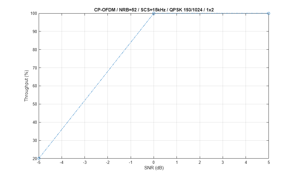
測定したスループットを表示します。これは、使用可能なリソースを所与とするリンクの最大スループットがデータ伝送に占める割合として計算されます。
figure;
plot(simParameters.SNRIn,simThroughput*100./maxThroughput,'o-.')
xlabel('SNR (dB)'); ylabel('Throughput (%)'); grid on;
if (simParameters.PUSCH.TransformPrecoding)
    ofdmType = 'DFT-s-OFDM';
else
    ofdmType = 'CP-OFDM';
end
title(sprintf('%s / NRB=%d / SCS=%dkHz / %s %d/1024 / %dx%d', ...
    ofdmType,simParameters.Carrier.NSizeGrid,simParameters.Carrier.SubcarrierSpacing, ...
    simParameters.PUSCH.Modulation, ...
    round(simParameters.PUSCHExtension.TargetCodeRate*1024),simParameters.NTxAnts,simParameters.NRxAnts));

% Bundle key parameters and results into a combined structure for recording
simResults.simParameters = simParameters;
simResults.simThroughput = simThroughput;
simResults.maxThroughput = maxThroughput;
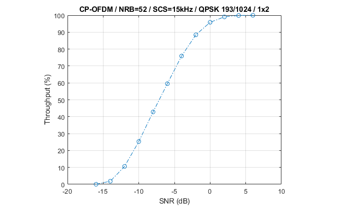
次の Figure は、10,000 サブフレーム (NFrames = 1000、SNRIn = -16:2:6) のシミュレーションで取得したスループットの結果を示しています。
参考文献
3GPP TS 38.211. "NR; Physical channels and modulation." 3rd Generation Partnership Project; Technical Specification Group Radio Access Network.
3GPP TS 38.212. "NR; Multiplexing and channel coding." 3rd Generation Partnership Project; Technical Specification Group Radio Access Network.
3GPP TS 38.213. "NR; Physical layer procedures for control." 3rd Generation Partnership Project; Technical Specification Group Radio Access Network.
3GPP TS 38.214. "NR; Physical layer procedures for data." 3rd Generation Partnership Project; Technical Specification Group Radio Access Network.
3GPP TR 38.901. "Study on channel model for frequencies from 0.5 to 100 GHz." 3rd Generation Partnership Project; Technical Specification Group Radio Access Network.
ローカル関数
function validateNumLayers(simParameters)
% Validate the number of layers, relative to the antenna geometry

    numlayers = simParameters.PUSCH.NumLayers;
    ntxants = simParameters.NTxAnts;
    nrxants = simParameters.NRxAnts;
    antennaDescription = sprintf('min(NTxAnts,NRxAnts) = min(%d,%d) = %d',ntxants,nrxants,min(ntxants,nrxants));
    if numlayers > min(ntxants,nrxants)
        error('The number of layers (%d) must satisfy NumLayers <= %s', ...
            numlayers,antennaDescription);
    end

    % Display a warning if the maximum possible rank of the channel equals
    % the number of layers
    if (numlayers > 2) && (numlayers == min(ntxants,nrxants))
        warning(['The maximum possible rank of the channel, given by %s, is equal to NumLayers (%d).' ...
            ' This may result in a decoding failure under some channel conditions.' ...
            ' Try decreasing the number of layers or increasing the channel rank' ...
            ' (use more transmit or receive antennas).'],antennaDescription,numlayers); %#ok<SPWRN>
    end

end

function plotLayerEVM(NSlots,nslot,pusch,siz,puschIndices,puschSymbols,puschEq)
% Plot EVM information

    persistent slotEVM;
    persistent rbEVM
    persistent evmPerSlot;

    if (nslot==0)
        slotEVM = comm.EVM;
        rbEVM = comm.EVM;
        evmPerSlot = NaN(NSlots,pusch.NumLayers);
        figure;
    end
    evmPerSlot(nslot+1,:) = slotEVM(puschSymbols,puschEq);
    subplot(2,1,1);
    plot(0:(NSlots-1),evmPerSlot,'o-');
    xlabel('Slot number');
    ylabel('EVM (%)');
    legend("layer " + (1:pusch.NumLayers),'Location','EastOutside');
    title('EVM per layer per slot');

    subplot(2,1,2);
    [k,~,p] = ind2sub(siz,puschIndices);
    rbsubs = floor((k-1) / 12);
    NRB = siz(1) / 12;
    evmPerRB = NaN(NRB,pusch.NumLayers);
    for nu = 1:pusch.NumLayers
        for rb = unique(rbsubs).'
            this = (rbsubs==rb & p==nu);
            evmPerRB(rb+1,nu) = rbEVM(puschSymbols(this),puschEq(this));
        end
    end
    plot(0:(NRB-1),evmPerRB,'x-');
    xlabel('Resource block');
    ylabel('EVM (%)');
    legend("layer " + (1:pusch.NumLayers),'Location','EastOutside');
    title(['EVM per layer per resource block, slot #' num2str(nslot)]);

    drawnow;

end

function [channel,simParameters] = createChannel(simParameters,waveformInfo)

    % Constructed the CDL or TDL channel model object
    if contains(simParameters.DelayProfile,'CDL','IgnoreCase',true)

        channel = nrCDLChannel; % CDL channel object

        % Swap transmit and receive sides as the default CDL channel is
        % configured for downlink transmissions.
        swapTransmitAndReceive(channel);

        % Turn the number of antennas into antenna panel array layouts. If
        % NRxAnts is not one of (1,2,4,8,16,32,64,128,256,512,1024), its value
        % is rounded up to the nearest value in the set. If NTxAnts is not 1 or
        % even, its value is rounded up to the nearest even number.
        channel = hArrayGeometry(channel,simParameters.NTxAnts,simParameters.NRxAnts,'uplink');
        simParameters.NTxAnts = prod(channel.TransmitAntennaArray.Size);
        simParameters.NRxAnts = prod(channel.ReceiveAntennaArray.Size);
    else
        channel = nrTDLChannel; % TDL channel object

        % Configure the channel to automatically select a sample rate for
        % generating channel coefficients
        channel.PathGainSampleRate = 'auto';

        % Swap transmit and receive sides as the default TDL channel is
        % configured for downlink transmissions
        swapTransmitAndReceive(channel);

        % Set the channel geometry
        channel.NumTransmitAntennas = simParameters.NTxAnts;
        channel.NumReceiveAntennas = simParameters.NRxAnts;
    end

    % Assign simulation channel parameters and waveform sample rate to the
    % object, and specify OFDM channel response as the channel response output
    % so that perfect channel estimate is calculated while filtering the signal
    channel.DelayProfile = simParameters.DelayProfile;
    if ~strcmp(channel.DelayProfile,"None")
        channel.DelaySpread = simParameters.DelaySpread;
        channel.MaximumDopplerShift = simParameters.MaximumDopplerShift;
        channel.SampleRate = waveformInfo.SampleRate;
    end
    channel.ChannelResponseOutput = 'ofdm-response';

end