Automate Testing for UAV Package Delivery Example
This example shows how to edit requirements, link requirements to their implementation in a model, and verify their functionality in the context of a UAV application. The components of the model and requirements include guidance and control of a UAV implemented by the UAV Package Delivery example.
Introduction
The UAV Package Delivery example shows through incremental design iterations how to implement a small multicopter simulation to takeoff, fly, and land at a different location in a city environment. In this example we go through the process of editing a small but representative requirement set, linking these requirements to sections in the model that implement these requirements, and finally validate these through a test suite.
Requirements Review
To load the required project and files, click Open Live Script or run the openExample function.
openExample('uav/AutomateTestingForUAVPackageDeliveryExample')
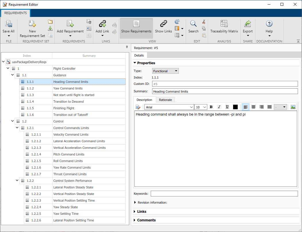
Requirements Toolbox™ lets you author, analyze, and manage requirements within Simulink™. This example contains twenty functional requirements defined for the Guidance and Control of a UAV flight controller. Open the provided Simulink project and the requirement set. Alternatively, you can also open the file from the Requirements tab of the Requirements Manager app in Simulink.
prj = openProject("verifications");
open('uavPackageDeliveryReqs.slreqx')
Requirements are separated into Guidance and Control sections. These requirements map directly to sections in the multirotor model of the UAV Package Delivery example. Look through the list of requirements and click items to see and edit details on the right.
Linking Requirements to Implementation
Requirements Toolbox enables you to link each individual requirement to the Simulink model component that implements such requirement. To link requirements, first open the multirotor model.
open_system('MultirotorModel')Enter the requirements perspective by clicking in the Perspectives control in the lower-right corner of the model canvas.
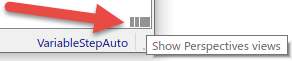
Select the Requirements perspective.

In the requirements perspective, navigate to the Guidance Logic and inspect some if the guidance requirements are implemented. Requirements #5 and #6 are labeled in gray. The heading and yaw command limits are implemented by the Waypoint Follower block.
open_system('MultirotorModel/Guidance Logic/Waypoint Guidance/Guidance Stateflow/Guidance Mode Selector/GuidanceLogic.WP')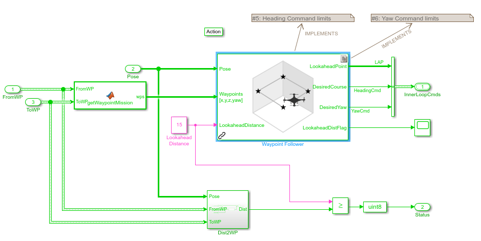
Alternatively, you can navigate to the implementation of each requirement from the Links section of each requirement in the requirement editor. Open the Requirement Editor. Select a functional requirement and navigate to the Links >> Implemented by section in the Details tab on the right.
open('uavPackageDeliveryReqs.slreqx')
Click on Requirement #19 (Index 1.2.1.4). In the Details tab under Links, click the theta_limit link to go to where the requirement is implemented in the multirotor model. The theta Limit block implements this requirement.

Automate Testing
To ensure each of the requirements is met, this example includes three automatic tests to run on the model. To see how these tests are implemented, open the test file in the Test Manager. You should see two test suites, GuidanceLogicSuite and ControlSystemTuner.
uiopen('MultirotorModelTest.mldatx',1)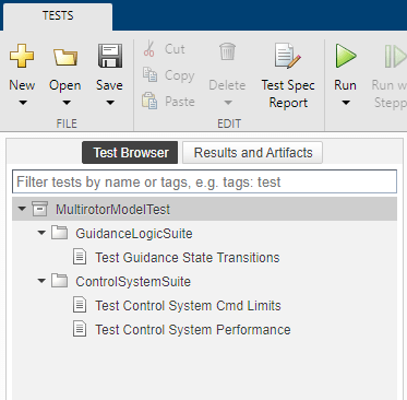
Testing the Guidance Logic
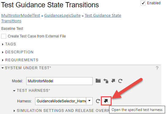
The Test Guidance State Transitions test makes use of GuidanceModeSelector_Harness Simulink model. The test model contains a Signal Editor with a pre-defined set of inputs to test all the phases of the guidance logic state machine, from takeoff to land.
To validate the requirements are met during simulation, the test implements six Assess Temporal Logic by Using Temporal Assessments (Simulink Test) and links each of these with a requirement.

Testing the Control System
The Control System test suite consists of two tests. One focused on testing all the command limits of the controller and the other assessing the controller performance. Both tests make use of ControlSystem_Harness Simulink model configured to drive the control system under some reasonable inputs and evaluate the response.

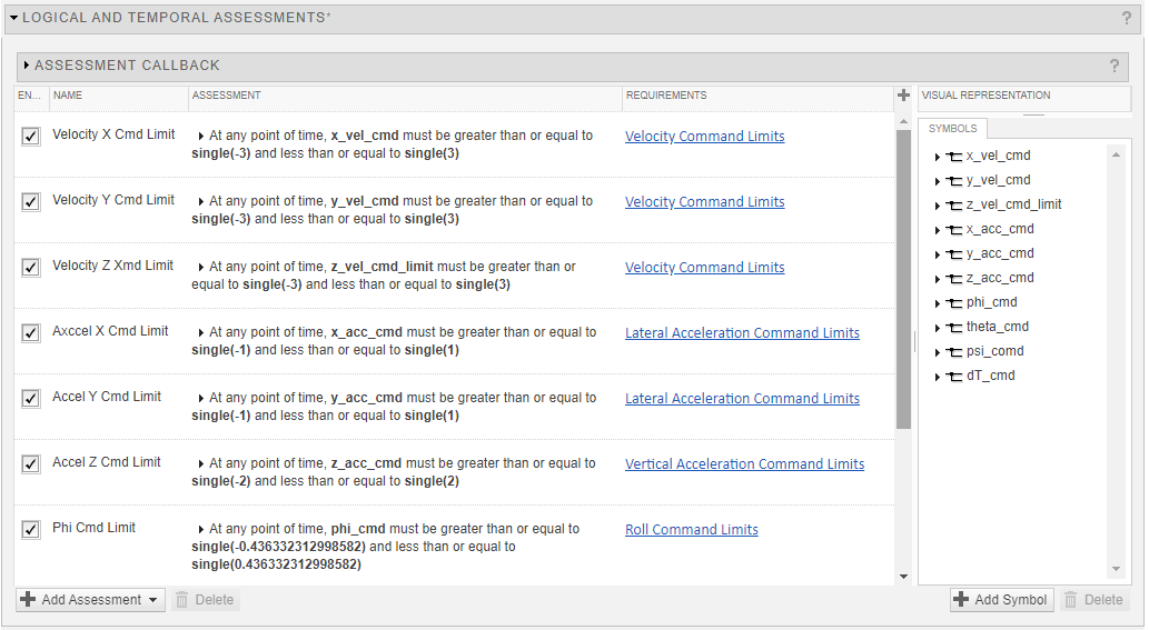
The Test Control System Cmd Limits test implements ten Assess Temporal Logic by Using Temporal Assessments (Simulink Test) assessments to make sure all commands in the control system are properly saturated to values established by the requirements. These assessments are linked to the corresponding requirements.

The Test Control System Performance test uses a Baseline Testing (Simulink Test) to assess whether the control system is within the bounds or diverges from a prerecorded baseline.
Running All Tests
To run both test suites, click Run on the Test Manager toolstrip. Once the tests run, you will see the results status in the Results and Artifacts tree.

Validating Requirements
As a final step, open the Requirement Editor and enable the Implementation State and Validation Status columns from the toolstrip. The column colors indicate whether each requirement has been implemented and verified by a test.

