Import and Export Architecture Models
To build a System Composer™ model, you can import information about components, ports, and connections in a predefined format using MATLAB® table objects. You can extend these tables and add information like applied stereotypes, property values, linked model references, variant components, interfaces, requirement links, and parameters.
Similarly, you can export information about components, hierarchy of components, ports on components, connections between components, linked model references, variants, stereotypes on elements, interfaces, requirement links, and parameters.
Tip
To learn more about how System Composer concepts apply to systems engineering design, see System Composer Concepts.
Define Basic Architecture
The minimum required structure for a System Composer model consists of these sets of information:
Components table
Ports table
Connections table
To import additional elements, you need to add columns to the tables and add specific values for these elements.
Components Table
The information about components is passed as values in a MATLAB table against predefined column names, where:
Nameis the component name.IDis a user-defined ID used to map child components and add ports to components.ParentIDis the parent component ID.
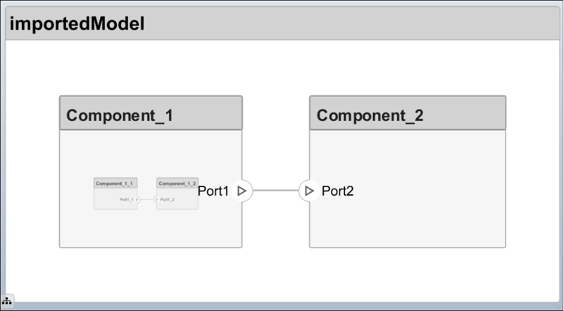
For example, Component_1_1 and Component_1_2 are children of Component_1.
| Name | ID | ParentID |
|---|---|---|
root | 0 | |
Component_1 | 1 | 0 |
Component_1_1 | 2 | 1 |
Component_1_2 | 3 | 1 |
Component_2 | 4 | 0 |
Name = {'root';'Component_1';'Component_1_1';'Component_1_2';'Component_2'};
ID = {'0';'1';'2';'3';'4'};
ParentID = {'';'0';'1';'1';'0'};
components = table(Name,ID,ParentID)
components =
5×3 table
Name ID ParentID
_________________ _____ __________
{'root' } {'0'} {0×0 char}
{'Component_1' } {'1'} {'0' }
{'Component_1_1'} {'2'} {'1' }
{'Component_1_2'} {'3'} {'1' }
{'Component_2' } {'4'} {'0' }Ports Table
The information about ports is passed as values in a MATLAB table against predefined column names, where:
Nameis the port name.Directioncan be one ofInput,Output, orPhysical.IDis a user-defined port ID used to map ports to port connections.CompIDis the ID of the component to which the port is added. It is the component passed in the components table.
| Name | Direction | ID | CompID |
|---|---|---|---|
Port1 | Output | 1 | 1 |
Port2 | Input | 2 | 4 |
Port1_1 | Output | 3 | 2 |
Port1_2 | Input | 4 | 3 |
Name = {'Port1';'Port2';'Port1_1';'Port1_2'};
Direction = {'Output';'Input';'Output';'Input'};
ID = {'1';'2';'3';'4'};
CompID = {'1';'4';'2';'3'};
ports = table(Name,Direction,ID,CompID)
ports =
4×4 table
Name Direction ID CompID
___________ __________ _____ ______
{'Port1' } {'Output'} {'1'} {'1'}
{'Port2' } {'Input' } {'2'} {'4'}
{'Port1_1'} {'Output'} {'3'} {'2'}
{'Port1_2'} {'Input' } {'4'} {'3'} Connections Table
The information about connections is passed as values in a MATLAB table against predefined column names, where:
Nameis the connection name.IDis connection ID used to check that the connections are properly created during the import process.Kindis the kind of connection specified byDataby default orPhysical. TheKindcolumn is optional and will default toDataif undefined.SourcePortIDis the ID of the source port.DestPortIDis the ID of the destination port.PortIDsare a comma-separated list of port IDs for physical ports that support nondirectional connections.
| Name | Kind | ID | SourcePortID | DestPortID | PortIDs |
|---|---|---|---|---|---|
Conn1 | Data | 1 | 1 | 2 | |
Conn2 | Data | 2 | 3 | 4 |
Name = {'Conn1';'Conn2'};
Kind = {'Data';'Data'};
ID = {'1'; '2'};
SourcePortID = {'1';'3'};
DestPortID = {'2';'4'};
PortIDs = {'';''};
connections = table(Name,Kind,ID,SourcePortID,DestPortID,PortIDs)
connections =
2×6 table
Name Kind ID SourcePortID DestPortID PortIDs
_________ ________ _____ ____________ __________ __________
{'Conn1'} {'Data'} {'1'} {'1'} {'2'} {0×0 char}
{'Conn2'} {'Data'} {'2'} {'3'} {'4'} {0×0 char} Import Basic Architecture
Import the basic architecture from the tables created above into System Composer from the MATLAB Command Window using the importModel function.
systemcomposer.importModel("importedModel",components,ports,connections);The basic architecture model opens.
Tip
The tables do not include information about the model's visual layout. You can arrange the components manually or use Format > Layout > Auto Arrange.
Extend Basic Architecture Import
You can import other model elements into the basic structure tables.
Import Data Interfaces and Map Ports to Interfaces
To define the data interfaces, add interface names in the ports table to associate ports to corresponding portInterfaces table. Create a table similar to components, ports, and connections. Information like interface name, associated element name along with data type, dimensions, units, complexity, minimum, and maximum values are passed to the importModel function in a table format shown below.
| Name | ID | ParentID | DataType | Dimensions | Units | Complexity | Minimum | Maximum |
|---|---|---|---|---|---|---|---|---|
interface1 | 1 | DataInterface | ||||||
elem1 | 2 | 1 | interface2 | |||||
interface2 | 3 | DataInterface | ||||||
elem2 | 4 | 1 | double | 1 | "" | real | "[]" | "[]" |
elem3 | 5 | 1 | valueType | 3 | cm | real | 0 | 100 |
valueType | 6 | int32 | 3 | cm | real | 0 | 100 | |
interface3 | 7 | PhysicalInterface | ||||||
elec | 8 | 7 | Connection: foundation.electrical.electrical | |||||
mech | 9 | 7 | Connection: foundation.mechanical.mechanical.rotational |
Data interfaces interface1 and interface2 are defined with data elements elem1 and elem2 under interface1. Data element elem2 is typed by interface2, inheriting its structure. For more information, see Nest Interfaces to Reuse Data.
Note
Owned interfaces cannot be nested. You cannot define an owned interface as the data type of data elements. For more information, see Define Owned Interfaces Local to Ports.
This data interface interface1 includes a data element elem3, which is typed by a value type valueType and inherits its properties. For more information, see Create Value Types as Interfaces.
This physical interface interface3 includes physical elements elec and mech, which are typed under their respective physical domains. For more information, see Specify Physical Interfaces on Ports.
To map the added data interface to ports, add the column InterfaceID in the ports table and specify the data interface to be linked. For example, interface1 is mapped to Port1 as shown below.
| Name | Direction | ID | CompID | InterfaceID |
|---|---|---|---|---|
Port1 | Output | 1 | 1 | interface1 |
Port2 | Input | 2 | 4 | interface2 |
Port1_1 | Output | 3 | 2 | "" |
Port1_2 | Input | 4 | 3 | interface1 |
Import Variant Components, Stateflow Behaviors, or Reference Components
You can add variant components just like any other component in the
components table, except you specify the name of the active variant.
Add choices as child components to the variant components. Specify the variant choices as
string values in the VariantControl column. You can enter expressions in
the VariantCondition column. For more information, see Create
Variants.
Add a variant component VarComp using component type Variant with choices Choice1 and Choice2. Set Choice2 as the active choice.
To add a referenced Simulink® model, change the component type to Behavior and specify the reference model name simulink_model.
To add a Stateflow® chart behavior on a component, change the component type to StateflowBehavior. If System Composer does not detect a license or installation of Stateflow, a Composition component is imported instead.
| Name | ID | ParentID | ReferenceModelName | ComponentType | ActiveChoice | VariantControl | VariantCondition |
|---|---|---|---|---|---|---|---|
root | 0 | ||||||
Component1 | C1 | 0 | simulink_model | Behavior | |||
VarComp | V2 | 0 | Variant | Choice2 | |||
Choice1 | C6 | V2 | petrol | ||||
Choice2 | C7 | V2 | diesel | ||||
Component3 | C3 | 0 | StateflowBehavior | ||||
Component1_1 | C4 | C1 | |||||
Component1_2 | C5 | C1 |
Pass the modified components table along with the ports and connections tables to the importModel function.
Apply Stereotypes and Set Property Values on Imported Model
To apply stereotypes on components, ports, and connections, add a StereotypeNames column to the components table. To set the properties for the stereotypes, add a column with a name defined using the profile name, stereotype name, and property name. For example, name the column UAVComponent_OnboardElement_Mass for a UAVComponent profile, a OnBoardElement stereotype, and a Mass property.
You set the property values in the format value{units}. Units and values are populated from the default values defined in the loaded profile file. For more information, see Define and Style Stereotypes in Profiles.
| Name | ID | ParentID | StereotypeNames | UAVComponent_OnboardElement_Mass | UAVComponent_OnboardElement_Power |
|---|---|---|---|---|---|
root | 0 | ||||
Component_1 | 1 | 0 | UAVComponent.OnboardElement | 0.93{kg} | 0.65{mW} |
Component_1_1 | 2 | 1 | |||
Component_1_2 | 3 | 1 | UAVComponent.OnboardElement | 0.93{kg} | "" |
Component_2 | 4 | 0 |
Assign Requirement Links on Imported Model
To assign requirement links to the model, add a requirementLinks table with these required columns:
Labelis the name of the requirement.IDis the ID of the requirement.SourceIDis the architectural element to which the requirement is attached.DestinationTypeis how requirements are saved.DestinationIDis where the requirement is located.Typeis the requirement type.
For more information, see Manage Requirements.
| Label | ID | SourceID | DestinationType | DestinationID | Type |
|---|---|---|---|---|---|
rset#1 | 1 | components:1 | linktype_rmi_slreq | C:\Temp\rset.slreqx#1 | Implement |
rset#2 | 2 | components:0 | linktype_rmi_slreq | C:\Temp\rset.slreqx#2 | Implement |
rset#3 | 3 | ports:1 | linktype_rmi_slreq | C:\Temp\rset.slreqx#3 | Implement |
rset#4 | 4 | ports:3 | linktype_rmi_slreq | C:\Temp\rset.slreqx#4 | Implement |
A Requirements Toolbox™ license is required to import requirement links into a System Composer architecture model.
Specify Elements on Architecture Port
In the connections table, you can specify different kinds of signal interface elements as source elements or destination elements. Connections can be formed from a root architecture port to a component port, from a component port to a root architecture port, or between two root architecture ports of the same architecture.
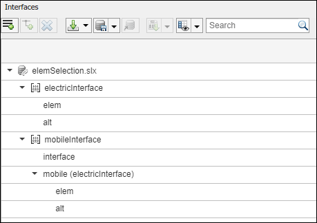
The nested interface element mobile.elem is the source element for the connection between an architecture port and a component port. The nested element mobile.alt is the destination element for the connection between an architecture port and a component port. The interface element mobile and the nested element mobile.alt are source elements for the connection between two architecture ports of the same architecture.
For more information, see Access Interface Elements Using Port Elements.
| Name | ID | SourcePortID | DestPortID | SourceElement | DestinationElement |
|---|---|---|---|---|---|
RootToComp1 | 1 | 5 | 4 | mobile.elem | |
RootToComp2 | 2 | 5 | 1 | mobile.alt | |
Comp1ToRoot | 3 | 2 | 6 | interface | |
Comp2ToRoot | 4 | 3 | 6 | mobile.alt | |
RootToRoot | 5 | 5 | 6 | mobile,mobile.alt |
Import Parameters with Parameter Value Types
In the parameters table, you can specify parameters and their values. Parameters can exist on the architectures of components and then be promoted to the root architecture of the model.
For parameters on Reference Component blocks, the parameters table shows the minimum set of columns because the complete parameter value type is defined on the referenced model. The minimum set of columns are:
Nameis the name of the parameter.IDis the ID of the parameter.Parentis the parent type (ComponentorArchitecture) with a colon and then the parent ID.Valueis the parameter value.
For more information, see Author Parameters in System Composer Using Parameter Editor.
| Name | ID | Parent | Value | Units | Type | Complexity | Minimum | Maximum | PromotedTo |
|---|---|---|---|---|---|---|---|---|---|
Pressure | 1 | Component:1 | 20 | psi | double | real | 0 | 100 | Component:0 |
Define Architecture Domain for Software Architectures
To specify that the architecture to be imported is a software architecture, specify the domain field of the import structure as "Software". For more information, see Import and Export Software Architectures.
Export Architecture
To export a model, pass the model name as an argument to the exportModel function. The function returns a structure containing tables: components, ports, connections, portInterfaces, requirementLinks, and parameters, and the field domain that is a character vector that represents the type of architecture being exported. The value of domain is 'System' for architecture models or 'Software' for software architecture models.
exportedSet = systemcomposer.exportModel(modelName)
You can export the set to MATLAB tables and then convert those tables to external file formats, including Microsoft® Excel® or databases.
exportedSet =

  struct with fields:

          components: [3×4 table]
               ports: [3×5 table]
         connections: [1×4 table]
      portInterfaces: [3×9 table]
    requirementLinks: [4×15 table]
          parameters: [6×9 table]
              domain: 'System'
If you import requirements to the model using an external file, in order to export and reimport those requirements, redirect reference requirement links within the model.
You can use the systemcomposer.updateLinksToReferenceRequirements function in System Composer to make the requirement links point to imported referenced requirements instead of external documents.
See Also
Apps
- Requirements Editor (Requirements Toolbox) | Requirements Manager (Requirements Toolbox)
Functions
importModel|exportModel|systemcomposer.io.ModelBuilder|systemcomposer.updateLinksToReferenceRequirements