電力網
電力システム ネットワークをモデル化し、電力潮流と高調波を解析する方法を学習します。
注目の例
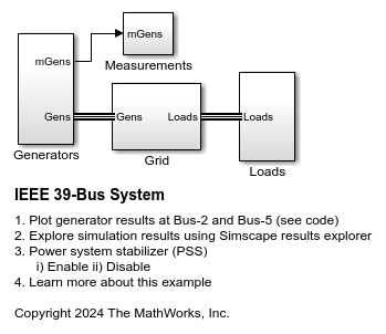
IEEE 39 母線システム
この例では、39 母線の三相電力システム ネットワークをモデル化する方法について説明します。この例は、IEEE のベンチマーク テスト ケースに基づいています。詳細については、Hiskens [1] の「IEEE PES Task Force on Benchmark Systems for Stability Controls」を参照してください。
- R2024b 以降
- モデルを開く
Model Static Var Compensator Using Thyristor-Switched Capacitor and Thyristor-Controlled Reactor
Models a static var compensator (SVC) using thyristor-switched capacitors (TSC) and a thyristor-controlled reactor (TCR).
- R2024a 以降
- モデルを開く
Model Static Synchronous Compensator Using Voltage Source Converter
Models a hybrid var compensator that includes a static synchronous compensator (STATCOM) and a thyristor-switched capacitor (TSC).
- R2024a 以降
- モデルを開く
Design, Operate, and Control Remote Microgrid
Develop, evaluate, and operate a remote microgrid. You also evaluate the microgrid and controller operations against various standards, including IEEE® Std 2030.9-2019, IEC TS 62898-1:2017 and IEEE Std 2030.7-2017. The planning objectives in the design of the remote microgrid include power reliability, renewable power usage, and reduction in diesel consumption. The key indices for economic benefits for the remote microgrid include life-cycle cost, net revenue, payback period, and internal rate of return. You can download this model in MATLAB® or access it from MATLAB Central File Exchange and GitHub®.
- R2023b 以降
- ライブ スクリプトを開く
グリッド形成コンバーターの設計と解析
この例では、13 個の事前定義されたテスト シナリオでグリッド形成 (GFM) コンバーターの性能を設計して解析する方法を示します。その後、テスト結果をグリッド コード規格と比較して、望ましい運用とコンプライアンスを確保できます。この例の GFM コンバーターは、代替慣性エミュレーション手法、構成可能な制御ループ、異なる電流制限手法を提供し、幅広い回路網の強度に適しています。このモデルは MATLAB® でダウンロードするか、MATLAB Central File Exchange と GitHub® からアクセスできます。
- R2023b 以降
- ライブ スクリプトを開く
2 母線電力潮流
この例では、2 母線の三相電力システム ネットワークのモデルについて説明します。このモデルでは、Simscape™ Electrical™ の Load Flow Source ブロックのインスタンスを 3 つ使用します。そのうち 1 つはスイング母線として、1 つは PV 母線として、1 つは PQ 負荷として構成されています。PV 母線は、電圧が定格電圧の 1.025 倍になるように、また 80 MW の有効電力をネットワークに供給するように、出力を調整します。スイング母線は、伝送線路のもう一端の電圧を定格電圧の 1 倍になるように調整し、全体的な有効電力と無効電力が均等になるように、必要な電力をネットワークに供給します。Simscape 初期化ソルバーは、定常状態で開始するように、PV 母線とスイング母線の両方で必要な内部初期電圧の振幅と位相を特定します。
被覆がボンディングされた AC ケーブル
この例では、複数のπ型セクションで構成される三相ケーブル モデルを説明します。各相は導電性被覆で覆われています。導電性被覆は、ケーブルのどちらかの端で単純な抵抗を介して接地接続します。高電圧源は、電力ケーブルを介して不平衡抵抗負荷に電力を供給します。被覆は、直列ボンディングまたは交差ボンディングのどちらかになるように構成できます。π型セクションの数を設定することもできます。π型セクションの数を増やすと、精度は向上しますが、シミュレーション速度は遅くなります。収束を容易にするため、電圧源には内部インピーダンスが含まれています。
IEEE 9 母線電力潮流
この例では、9 母線の三相電力システム ネットワークのモデルについて説明します。この例は、IEEE® のベンチマーク テスト ケースに基づいています。詳細については、「Power System Control and Stability」 (P. M. Anderson および A. A. Fouad 著、IEEE Press、2003) を参照してください。Simscape™ は、発電機のうち 2 つを指定した電力および端子電圧に初期化し、残りのスイング母線発電機を指定した電圧のみを満たすように初期化します。結果の電力潮流の解は、シミュレーション後に各母線に付加されます。4 つの行はそれぞれ、pu 電圧、位相、有効電力、無効電力に相当します。母線 1 を見ると、スイング発電機が 76.4 MW の有効電力と 27.5 MVAr の無効電力をネットワークに供給していることが、注釈から確認できます。元のベンチマークとの違いは、使用されている伝送線路モデルと変圧器の構成によるものです。
電力潮流を使用した誘導モーターの初期化
この例では、電力潮流計算の一環として三相誘導モーターを初期化する方法を説明します。AC 回路網に直接接続されている誘導機を初期化する場合、定常状態では 1 つの自由度があり、これはシャフトのトルク、シャフトの動力、モーター回転数、電力のいずれか 1 つによって設定できます。
電力潮流を使用した同期機の初期化
この例では、電力潮流計算の一環として同期機を初期化する方法を説明します。同期機を初期化する場合は 2 つの自由度があり、これは回転子の角度、有効電力、無効電力、端子電圧のうちいずれか 2 つによって設定できます。制約される変数のペアはソース タイプのドロップダウン メニューで設定します。これには [スイング母線]、[PV 母線]、[PQ 母線] のオプションがあります。ここでは、pu 電圧を 1.02、位相を 0 度として、スイング母線用にマシンを構成します。
複数のコイル間が相互結合している RLC ラダー回路網の入力アドミタンス応答
この例では、複数のコイル間が相互結合した RLC コンポーネントで構成される 4 セクション ラダー回路網をモデル化する方法を説明します。このラダー回路網の表現を使用して、変圧器のディスク巻線をモデル化できます。ラダー回路網のセクション数は、巻線内のディスク数で決まります。各セクションで、巻線内の 2 枚または 3 枚のディスクをモデル化できます。
AC マイクログリッドにおける距離リレーによる保護
この例では、AC マイクログリッドの距離リレーをモデル化する方法を説明します。Relay ブロックは、インピーダンス リレー特性とモー リレー特性で構成されています。この例を使用して、さまざまな故障状態におけるインピーダンス リレーとモー リレーのパフォーマンスを調べることができます。いずれのリレーにも、地絡故障用と線間故障用の 2 種類のリレーがあります。
AC マイクログリッドにおける過電流リレーによる保護
この例では、AC マイクログリッドの過電流リレーをモデル化する方法を説明します。この例を使用して、マイクログリッドの過電流リレーの協調を調べることができます。Relay ブロックは、相保護と地絡保護の 2 つの保護ユニットで構成されています。相保護ユニットは、マイクログリッドを高い相電流から保護します。地絡保護ユニットは、マイクログリッドを高い地電流から保護します。この例の "relay2" ブロックは、"distribution_line2" ブロックを保護します。"relay1" ブロックは "distribution_line1" ブロックを保護し、"relay2" ブロックの予備としても機能します。"distribution_line2" ブロックで故障が発生したときに "relay2" ブロックが動作しない場合、指定された時間の経過後に "relay1" ブロックが動作してシステムを分離します。システムのトリップを防ぐために、"relay1" ブロックと "relay2" ブロックは、どのようなときでも 1 つのリレーのみが動作するように機能します。"relay2" ブロックの時間乗数設定または目的の動作時間のいずれかを指定できます。
AC/DC 混合システムの電力潮流
この例では、電力潮流アナライザーを使用して AC/DC 混合システムの電力潮流結果を確認する方法を説明します。この解析対象のモデルには、AC 電力潮流電源、三相整流器、および 3 つの負荷が含まれます。負荷の 1 つは AC で、1 つは DC 側で常時接続されており、1 つは DC 側で切り替えられます。
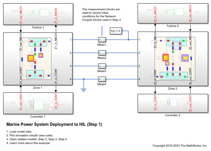
Marine Power System Deployment to HIL
A marine power system model suitable for multirate Hardware-In-the-Loop (HIL) deployment. The example uses the Simscape™ Network Couplers Library to split the model into separate Simulink® subsystems that you can deploy at different sample rates. This allows you to run parts of the system (here, for example, the turbines) with a slower sample time and reduce overall computational cost.
Microgrid Resynchronization with Main Grid
Resynchronize an islanded microgrid with the main grid by using a battery energy storage system (BESS). The model in this example comprises a medium voltage (MV) microgrid model with a battery energy storage system, a photovoltaic solar park (PV), and loads. The microgrid can operate both autonomously (islanded) or in synchronization with the main grid. In this example, the microgrid is first in islanded mode. The resynchronization function then synchronizes the microgrid to the main grid. Finally, the breaker closes to connect the microgrid to the main grid. After the resynchronization, the battery system performs a power dispatch and the loads are changed.
Microgrid Planned Islanding from Main Grid
Execute a microgrid planned islanding from the main grid by using a battery energy storage system (BESS). The model in this example comprises a medium voltage (MV) microgrid model with a BESS, a photovoltaic solar park (PV), and loads. The microgrid can operate both autonomously (islanded) or in synchronization with the main grid. In this example, the microgrid initially is in grid-connected mode. The planned islanding function controls the point of common coupling (PCC) power flow to zero. Finally, the breaker opens to disconnect the microgrid from the main grid. After the islanding, the battery system performs a power dispatch, and the loads are changed.
MATLAB Command
You clicked a link that corresponds to this MATLAB command:
Run the command by entering it in the MATLAB Command Window. Web browsers do not support MATLAB commands.
Web サイトの選択
Web サイトを選択すると、翻訳されたコンテンツにアクセスし、地域のイベントやサービスを確認できます。現在の位置情報に基づき、次のサイトの選択を推奨します:
また、以下のリストから Web サイトを選択することもできます。
最適なサイトパフォーマンスの取得方法
中国のサイト (中国語または英語) を選択することで、最適なサイトパフォーマンスが得られます。その他の国の MathWorks のサイトは、お客様の地域からのアクセスが最適化されていません。
南北アメリカ
- América Latina (Español)
- Canada (English)
- United States (English)
ヨーロッパ
- Belgium (English)
- Denmark (English)
- Deutschland (Deutsch)
- España (Español)
- Finland (English)
- France (Français)
- Ireland (English)
- Italia (Italiano)
- Luxembourg (English)
- Netherlands (English)
- Norway (English)
- Österreich (Deutsch)
- Portugal (English)
- Sweden (English)
- Switzerland
- United Kingdom (English)


