斜面を転がり下りる中実円柱
この例では、Spatial Contact Force ブロックを使用して、傾斜平面を転がり下りる車輪をモデル化するシステムの作成方法を説明します。
転がる車輪のモデル化
新しい Simscape™ Multibody™ モデルを作成するには、MATLAB® コマンド プロンプトに以下を入力します。
smnew
モデルに以下を追加します。
1 つの Rigid Transform ブロック
1 つの 6-DOF Joint ブロック
1 つの Cylindrical Solid ブロック
1 つの Spatial Contact Force ブロック
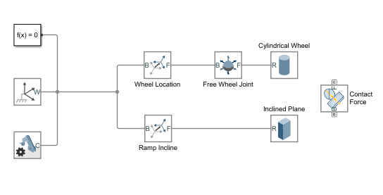
Scope、PS-Simulink Converter、および Simulink-PS Converter の各ブロックを削除します。以下の図に示すように、ブロックの名前を変更して、それらを接続します。
以下のプロパティを Wheel Location に割り当てます。
| Property | 値 |
|---|---|
| [Rotation] 、 [Method] | Aligned Axes |
| [Rotation] 、 [Pair 1] 、 [Follower] | +Z |
| [Rotation] 、 [Pair 1] 、 [Base] | -Y |
| [Rotation] 、 [Pair 2] 、 [Follower] | +X |
| [Rotation] 、 [Pair 2] 、 [Base] | +X |
| [Translation] 、 [Method] | None |
以下のプロパティを Ramp Incline に割り当てます。
| Property | 値 |
|---|---|
| [Rotation] 、 [Method] | Standard Axis |
| [Rotation] 、 [Axis] | +Y |
| [Rotation] 、 [Angle] | 5 度 |
| [Translation] 、 [Method] | Cartesian |
| [Translation] 、 [Offset] | [30 0 -15] cm |
以下のプロパティを Cylindrical Wheel に割り当てます。
| Property | 値 |
|---|---|
| [Geometry] 、 [Radius] | 5 cm |
| [Geometry] 、 [Length] | 4 cm |
| [Geometry] 、 [Export] 、 [Entire Geometry] | selected |
| [Inertia] 、 [Type] | Calculate from Geometry |
| [Inertia] 、 [Based on] | Density |
| [Inertia] 、 [Density] | 650 kg/m^3 |
| [Graphic] 、 [Type] | From Geometry |
| [Graphic] 、 [Visual Properties] | Simple |
| [Graphic] 、 [Visual Properties] 、 [Color] | [0.6 0.0 0.0] |
| [Graphic] 、 [Visual Properties] 、 [Opacity] | 1.0 |
| [Frames] 、 [Show Port R] | selected |
以下のプロパティを Inclined Plane に割り当てます。
| Property | 値 |
|---|---|
| [Geometry] 、 [Dimensions] | [90 20 5] cm |
| [Geometry] 、 [Export] 、 [Entire Geometry] | selected |
| [Inertia] 、 [Type] | Calculate from Geometry |
| [Inertia] 、 [Based on] | Density |
| [Inertia] 、 [Density] | 1000 kg/m^3 |
| [Graphic] 、 [Type] | From Geometry |
| [Graphic] 、 [Visual Properties] | Simple |
| [Graphic] 、 [Visual Properties] 、 [Color] | [0.4196 0.5569 0.1373] |
| [Graphic] 、 [Visual Properties] 、 [Opacity] | 1.0 |
| [Frames] 、 [Show Port R] | selected |
以下のプロパティを Contact Force に割り当てます。
| Property | 値 |
|---|---|
| [Normal Force] 、 [Stiffness] | 1e6 N/m |
| [Normal Force] 、 [Damping] | 1e3 N/(m/s) |
| [Normal Force] 、 [Normal Force: Transition Region Width] | 1e-4 m |
| [Frictional Force] 、 [Method] | Smooth Stick-Slip |
| [Frictional Force] 、 [Coefficient of Static Friction] | 0.3 |
| [Frictional Force] 、 [Coefficient of Dynamic Friction] | 0.3 |
| [Frictional Force] 、 [Critical Velocity] | 0.01 m/s |
| [Sensing] 、 [Separation Distance] | unselected |
| [Sensing] 、 [Normal Force] | unselected |
| [Sensing] 、 [Frictional Force Magnitude] | unselected |
[モデル化] タブで、[モデル設定] 、 [モデル設定] を選択して [コンフィギュレーション パラメーター] を開きます。[ソルバー] ペインの [ソルバーの詳細] で、以下を更新します。
| 最大ステップ サイズ: | 1e-3 |
| 絶対許容誤差: | 1e-3 |
この時点で、Cylindrical Wheel ブロックと Inclined Plane ブロックの両方にはジオメトリ端子がなければなりません。図に示すように、Inclined Plane ブロックと Cylindrical Wheel ブロックのジオメトリ端子を、Spatial Contact Force ブロックの base 端子と follower 端子にそれぞれ接続します。

[シミュレーション] タブで [実行] をクリックします。MATLAB ウィンドウで、Multibody Explorer が開き、円柱状の車輪が表面を転がり下りる様子を確認できます。より複雑なモデルを確認するには、Spatial Contact Force ブロックの使用 - バンパー カーを参照してください。