バリアント ソースとバリアント シンクの定義と構成
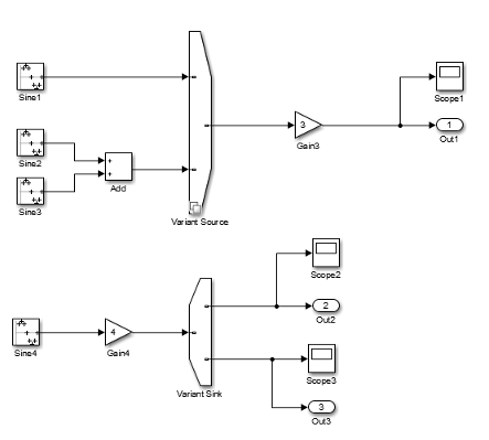
Simulink® では、モデル内のバリアントの選択のすべての可能な実装をグラフィカルに可視化するために使用できる 2 つのブロック Variant Source と Variant Sink が提供されています。この例では、Variant Source ブロックと Variant Sink ブロックを使用してバリアントの選択を構成する方法を示します。
Variant Source ブロックと Variant Sink ブロックでのバリアントの選択の表現
Variant Source ブロックと Variant Sink ブロックの入力端子と出力端子におけるそれぞれのバリアント条件によって、それらに接続されたブロックのアクティベーションおよびアクティベーション停止が決定されます。"バリアント制御" を使用して、バリアントの選択をアクティブにする条件を指定できます。それぞれのバリアントの選択がバリアント制御に関連付けられますが、1 つのバリアント制御のみが true として評価されます。バリアント条件が true と評価される場合、Simulink は対応するバリアントの選択をアクティブにします。また、最大で 1 つのバリアントの選択を既定の選択として指定できます。
[バリアント制御モード] パラメーターを使用してバリアント制御を指定するモードを選択できます。この例では [式] モードを使用します。ここでは、バリアント制御として、モデルのベース ワークスペースで定義されている Simulink.Parameter オブジェクトを含む boolean の条件式を指定します。
ヒント
各種のバリアント制御モードの詳細については、バリアント制御の紹介を参照してください。
バリアント条件式でサポートされるバリアント制御変数の種類の詳細については、Types of Variant Control Modes in Variant Blocksを参照してください。
Variant Source および Variant Sink ブロックをモデルに追加します。

Simulink ライブラリ ブラウザーからのブロックを使用して、バリアントの選択を表すソースとシンクを作成します。選択肢を Variant Source ブロックおよび Variant Sink ブロックの入力端子と出力端子に接続します。

MATLAB® コマンド ウィンドウで、次のコマンドを実行してバリアント制御変数を作成します。
V = Simulink.Parameter(1);
W = Simulink.Parameter(2);
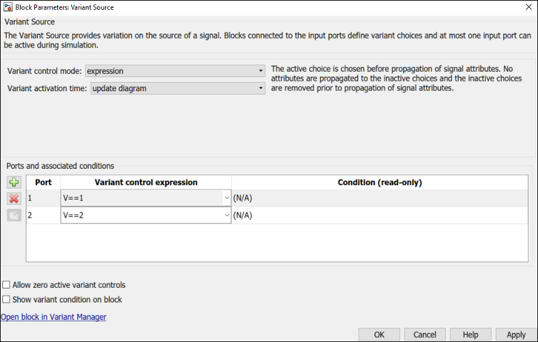
Variant Source ブロックの [ブロック パラメーター] ダイアログ ボックスを開きます。ブロックをダブルクリックするか、ブロックを右クリックして [ブロック パラメーター (Variant Source)] を選択します。
ヒント
すべてのブロック パラメーターの詳細については、Variant Source および Variant Sink を参照してください。
[ブロック パラメーター] ダイアログ ボックスの [端子および関連付けられている条件] テーブルには、Variant Source ブロックの入力端子に接続されたバリアントの選択ごとに 1 つの行があります。バリアント選択が存在しない場合、テーブルは空になります。
テーブルの左にあるボタンを使用して、テーブルの要素を変更できます。
アクション ボタン 新しい入力端子を追加します: 新しい入力端子をバリアントの選択として作成し、その新しい選択肢のエントリをテーブルに追加します。

選択した端子を削除します: 選択したバリアントの選択をブロックから削除し、そのバリアントの選択のエントリをテーブルから削除します。

選択されている Variant オブジェクトを作成/編集: 選択したバリアントの選択の
Simulink.VariantExpressionオブジェクトをベース ワークスペースで作成または編集し、Simulink.VariantExpressionオブジェクトのパラメーター ダイアログ ボックスを使用してバリアント条件を指定します。メモ
ベース ワークスペースを使用するモデルの場合、この操作によって
Simulink.VariantExpressionオブジェクトがベース ワークスペースに作成されます。このオブジェクトは現在の MATLAB セッションに対してのみ使用できます。データを永続的に保存するには、オブジェクトを MAT ファイルまたは MATLAB スクリプトに保存します。
[ブロック パラメーター] ダイアログ ボックスの [バリアント制御式] 列で、一方の選択に「
V==1」、もう一方に「V==2」と入力します。いずれかの選択を既定のバリアントとして指定するには、[バリアント制御式] リストから
[(既定の設定)]を選択します。trueと評価されるバリアント制御がない場合、Simulink はシミュレーションとコード生成に既定のバリアントを使用します。
[適用] をクリックします。
Variant Sink ブロックをダブルクリックします。[ブロック パラメーター] ダイアログ ボックスの [バリアント制御式] 列で、一方の選択に「
W==1」、もう一方に「W==2」と入力します。
[適用] をクリックします。
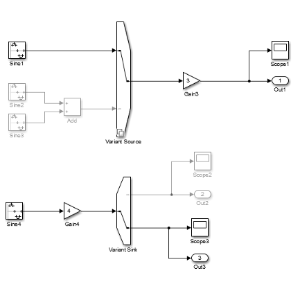
モデルのシミュレーションを実行します。Simulink はバリアント条件を伝播し、有効にするモデル コンポーネントを特定します。

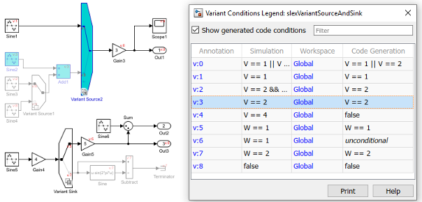
バリアントの各選択を有効にする条件を可視化できます。ツールストリップの [デバッグ] タブで、[情報のオーバーレイ] 、 [バリアント条件]を選択します。

[バリアント条件の凡例] ダイアログ ボックスで、ハイパーリンクされたバリアント条件の注釈をクリックすると、それぞれの条件によって有効になるモデルの部分が表示されます。
