Wireless Tire Pressure Monitoring System with Fault Logging
This example shows how to design, model, and simulate a distributed monitoring system. In this system, multiple sensors communicate wirelessly with a controller. The controller takes action when it detects a fault condition and maintains a log of fault conditions. The example uses a model of an automotive tire pressure monitoring system with identical pressure sensors at each wheel that communicate wirelessly with a controller in the vehicle using a unique device ID that is known to the controller. The controller checks the pressure readings against the acceptable range. If a pressure reading is out of range, or if the controller has lost communication with one of the sensors, the controller activates a warning lamp, and records the fault in a log.
Run this command to create and open a working copy of the project files for this example:
slexTirePressureMonitoringSystem

Model Overview
The model contains four identical tire pressure sensors modeled by multi-instanced Model blocks that represent sensors on the four tires of a vehicle. The sensors periodically send messages to the controller. Each message consists of a tire pressure reading and the device ID of the sensor. All messages are routed to the controller via a Message Merge block and are buffered by a Queue block.
Messages in Simulink® combine events with related data. Messages are used to model communication between components in a distributed system, such as the communication between the sensors and the controller in this system. See Simulink Messages Overview.
The controller may also receive communications from sensors on other vehicles nearby. The controller has the list of the device IDs of the relevant sensors so that it can determine which communications to examine and which ones to reject.
To model the external environment in which the system operates, the model contains a fifth instance of the sensor model, representing a tire pressure sensor on a nearby vehicle, and which transmits messages that are received by the controller.
Controller Unit

The controller receives discrete communications from each of the sensors as they are sent via wireless communication, middleware, or a combination of both. Each communication consists of a tire pressure reading from the physical hardware together with the unique device ID of the sensor unit. The combination of pressure data and device ID form a composite signal of different data types (double and character vector). This type of signal is reused throughout the model. Thus, defining a Simulink.Bus type for this combination makes sense. The communications may or may not be received periodically, so they are treated as asynchronous. The asynchronous communications are modeled as messages in Simulink, with the bus as the message payload.
The controller may also receive communications from sensors on other vehicles nearby. These communications are also modeled as messages with the same bus type. The controller model controllerCoreAlgorithm.slx receives as a model argument the list of the device IDs of the relevant sensors so that it can determine which communications to examine and which ones to reject.
Incoming communications from sensors are received and buffered in a Stateflow® chart and then passed to a MATLAB Function block. The MATLAB Function block checks each the device ID in each message against the valid device ID list, rejects messages with no match, and outputs these vectors at each time step:
A four-element logical vector indicating whether a current sensor reading was received from each tire
A four-element data vector containing the sensor readings
These vectors are passed to a for-each subsystem, which applies the same algorithm to each sensor. Both of these inputs to the for-each subsystem are partitioned, along with the valid device ID list.

The controller model arguments include:
The acceptable range for the tire pressure data measured by the sensors
How frequently the sensors are expected to transmit data in order not to be considered to have timed out.
Within the for-each subsystem, a Stateflow chart is used to model the temporal logic of checking for timeouts as well as to check whether the pressure reading is within the valid range.
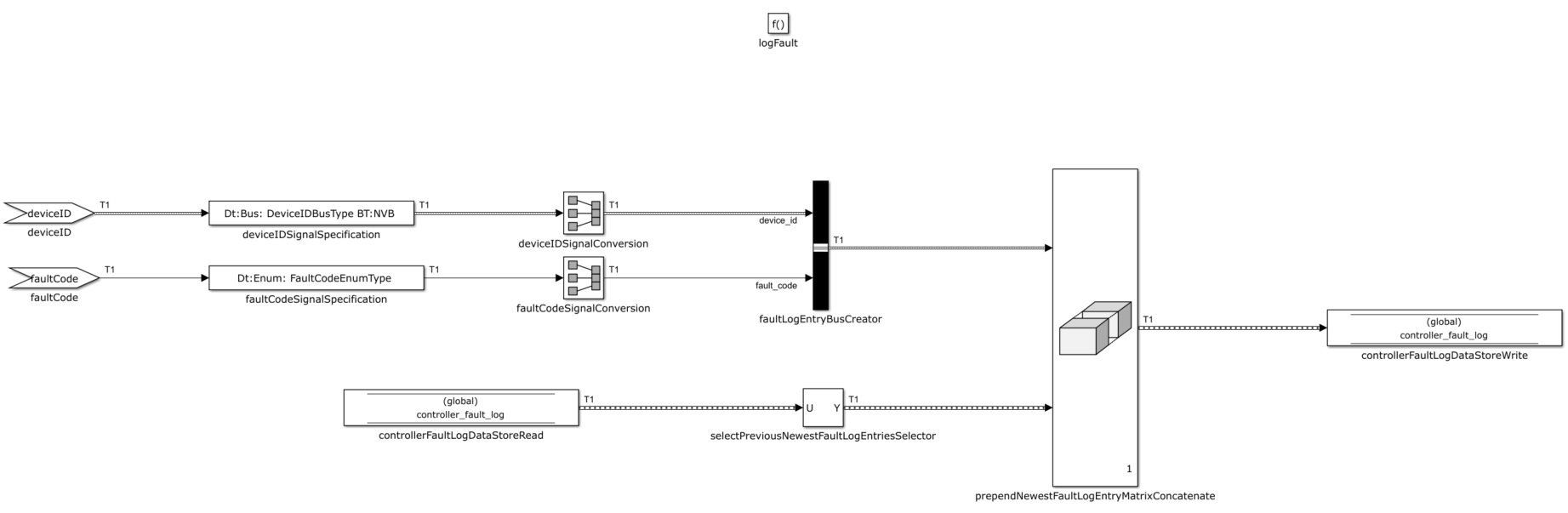
When the controller detects a fault, the fault is recorded in a fault log, which is modeled by a Data Store Memory block, representing an area of RAM in the controller. Each log entry consists of the device ID and the type of fault: pressure too high, pressure too low, lost contact with sensor. The type of fault is an enumerated data type defined for this purpose. The combination of device ID and type of fault used in the fault log entries form a composite signal type, is defined using a Simulink.bus type with these two fields. The Simulink function logFault performs the fault logging by prepending the new fault information to the fault log. The Stateflow chart calls this function each time it detects a fault.
The Stateflow chart receptionStatusChart outputs a logical signal for each of the possible fault conditions, and the for-each subsystem concatenates these output signals into logical vectors. These signals are combined with logical operators into a single, scalar, logical output for the controller that indicates the presence or absence of a fault condition. This signal can be used to trigger a warning lamp or audible alarm when there is a fault condition.
The list of acceptable sensor device IDs is an instance parameter of the controller model, as are the minimum and maximum acceptable values for tire pressure and the timeout interval. The controller algorithm can be deployed in different applications with different values of these parameters.
Sensor Units

Each sensor measures data from the physical environment, that is, tire pressure. In the sensor model, this input is modeled with a root Inport block. The pressure measurement is combined with the unique device ID into a bus signal using the Simulink.bus type defined for this purpose. The bus signal is the payload of the message output of the sensor, which is created by a Message Send block and sent to the root Outport. The sensors are designed to transmit readings periodically. However, the communications are treated as asynchronous to account for uncertainty in transmission and reception. Each message represents a discrete, asynchronous transmission sent through wireless communication, middleware, or a combination of both.
The unique device ID is an instance parameter of the sensor model, which is multi-instantiated to represent the multiple tires of the vehicle. The sensor models are identical apart from this instance parameter.
System Model
In the system model, the controller unit is represented by a referenced model, and the sensor units are represented by a multi-instantiated referenced model. The communication between the sensors and the controller is modeled with messages in Simulink. The messages are combined with a Message Merge block into a single channel and buffered by a Queue block that represents a queue in the reception firmware.
The inputs to the system are the sensor readings from the physical environment, which are fed into the input ports of the sensor models. Source blocks can be used to model sensor readings. Here, varying inputs are modeled using Sine Wave blocks, with a sample time based on the frequency of pressure measurements. The output of the system is the control signal, which indicates the presence or absence of a fault condition.
In addition to the control signal at the outport, the system maintains a log of recorded fault conditions. The log is internal to the system, but it represents in effect part of the system output that can be examined and tested.
An additional sensor model represents a sensor on a nearby vehicle. The transmissions of this sensor model can be received by the controller, though the device ID of this sensor is not on the list of valid device IDs used by the controller. This model is also driven by a Sine Wave block. The message outputs of this sensor unit are merged with the messages from the vehicle sensors and sent to the controller unit.
Data types such as Simulink.bus types and enumerated types that are used by the models are stored in a shared data dictionary commonData.sldd, which allows all models to have access to the definitions. See What Is a Data Dictionary?.
Simulating the Model
The Sine Wave blocks used as inputs are configured so that some inputs are outside the acceptable tire pressure range, which triggers a fault condition. After simulating the model, you can observe the results in the Simulation Data Inspector.
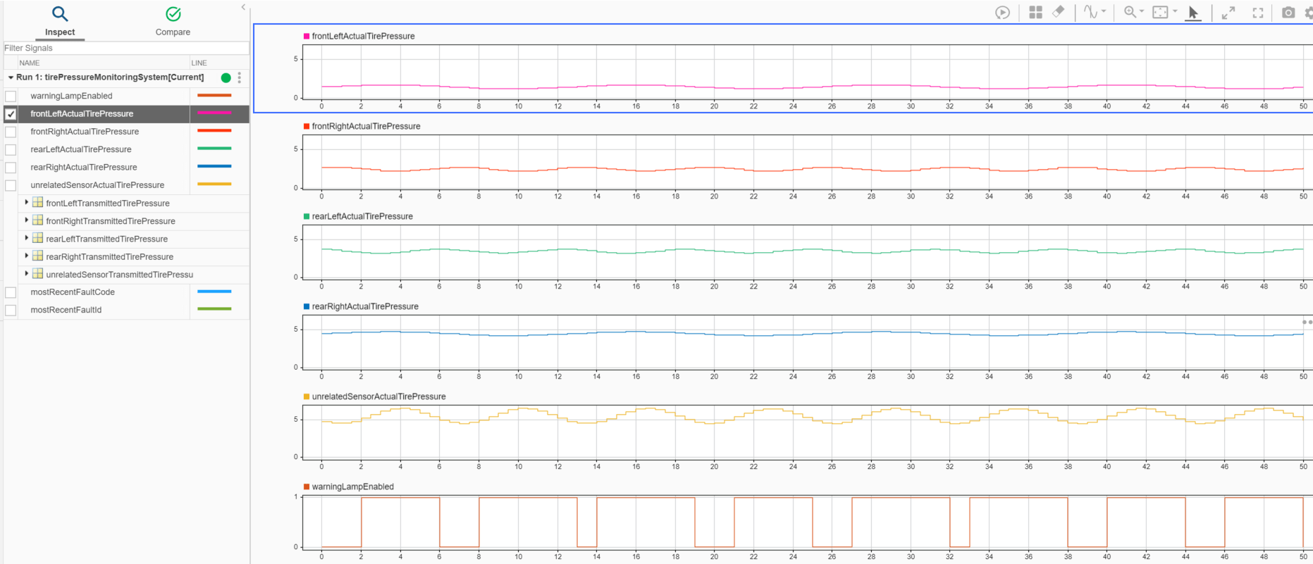
The bottom plot shows when the control signal that activates the warning lamp is enabled. The warning lamp is activated when the rear right tire pressure is in excess of the maximum acceptable value of 4.5 and when the front left tire pressure is less than the minimum acceptable value of 1.25, but the unrelated sensor does not trigger the warning lamp.
See Also
MATLAB Function | Simulink Function