Sign-Following Robot with ROS in Simulink
This example shows how to use Simulink® software to control a simulated robot running on a separate ROS-based simulator. You can run this example using a Docker® container or virtual machine.
In this example, you run a model that implements a sign-following algorithm and controls the simulated robot to follow a path based on signs in the environment. The algorithm receives the location information and camera information from the simulated robot, which is running in a separate ROS-based simulator. The algorithm detects the color of the sign and sends the velocity commands to turn the robot based on the color. In this example, the algorithm turns the robot to the left when it encounters a blue sign and to the right when it encounters a green sign. The robot stops when it encounters a red sign.
For an example that shows how to control a sign-following robot using ROS 2 or MATLAB®, see Sign Following Robot with ROS in MATLAB. To run this example you can use Docker or Virtual Machine.
Build ROS Docker Image
You can download the ROS Dockerfile by cloning ROS Toolbox Docker Files. Then, build a Docker image that has ROS and Gazebo installed by following these steps:
Open a Terminal in Linux and navigate to the "
ros-docker-support/ros_noetic/Ubuntu" folder.Build the Dockerfile by executing this command:
docker build -t noetic_docker_image_focal ros_humble/Ubuntu command. In this command,noetic_docker_image_focalis the docker image name.
This image is based on Ubuntu® Linux® and supports the sign-following robot examples in ROS Toolbox.
Start Robot Simulator
Start a ROS-based simulator for a differential-drive robot and configure the Simulink connection with the robot simulator.
Create a docker container by running this command in a Linux Terminal:
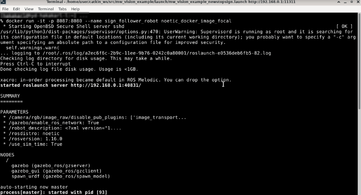
docker run -it -p 8087:8080 --name sign_follower_robot noetic_docker_image_focal
It creates a docker container and starts the Gazebo world in your Docker container.
You can use these options with the docker run command.
-it--- Start an interactive container.-p--- Publish the container ports to the host computer. In this case, port8087on the host maps to port8080on the docker container.--name--- Name the container. In this example you name the containersign_follower_robot.This image shows the command line output when you create a Docker container:
To view the Gazebo Sign Follower World, open any web browser and connect the host port you use to configure your Docker image. For this example, connect to localhost:8087.
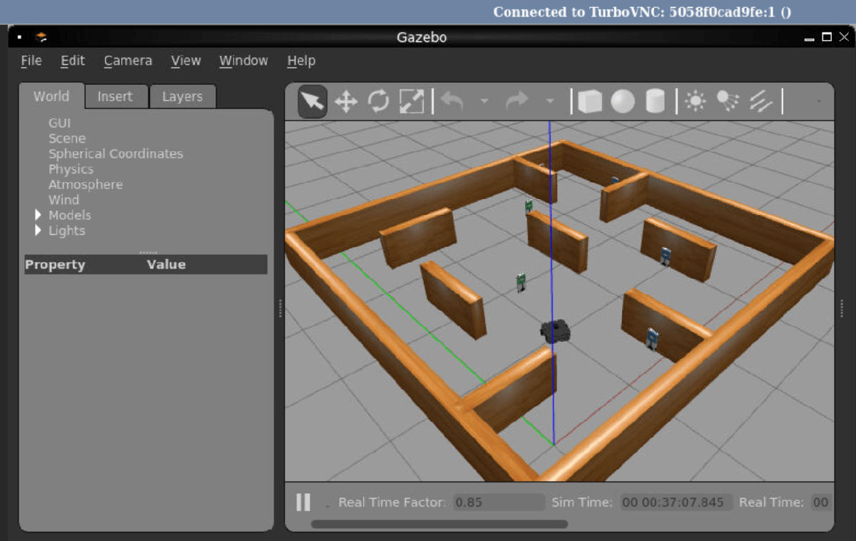
This figure shows the Gazebo Sign Follower World.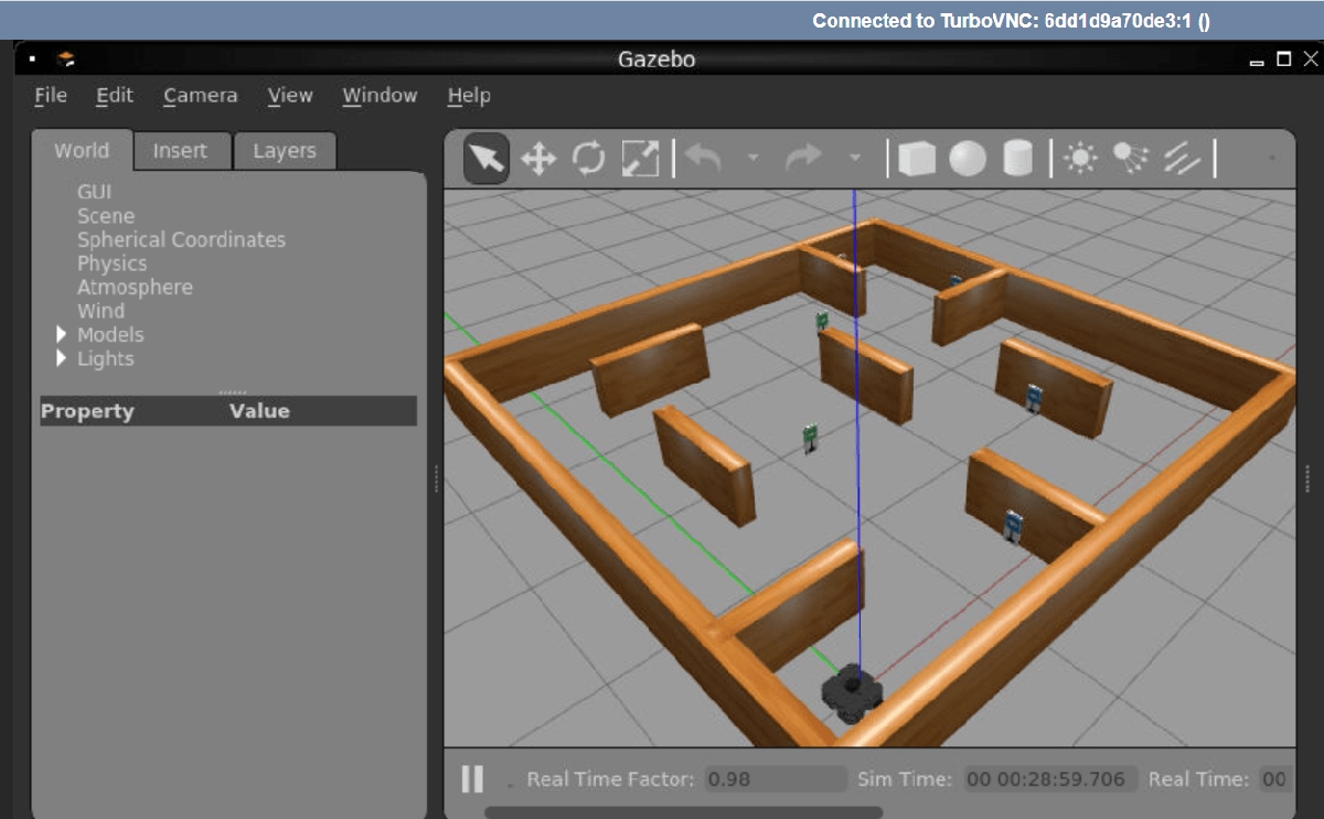
Get IP Address of Docker Container
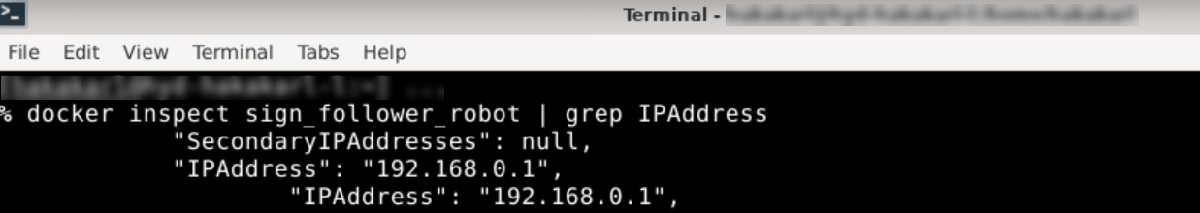
To get the IP address of the Docker container, execute this in a Terminal window.
docker inspect sign_follower_robot
This image shows the output of the docker inspect command when you pipe it to the grep command.
Start Robot Simulator in VM
Alternatively, you can run this example using a virtual machine (VM). You can download a VM image that already has ROS and Gazebo software installed. This virtual machine is based on Ubuntu® Linux® and supports the examples in ROS Toolbox.
Download and install the ROS Virtual Machine.
Launch the VM.
Start the Ubuntu® VM desktop.
In the Ubuntu desktop, click the Gazebo Sign Follower ROS icon to start the Gazebo world for this example.
Open Model and Configure Simulink
Setup the Simulink ROS preferences to communicate with the robot simulator.
Open the example model.
open_system("signFollowingRobotROS.slx");To configure the network settings for ROS.
From the Prepare section of the Simulation tab, select ROS Network.
Specify the IP address and port number of the ROS master in Gazebo. For this example, the ROS master in Gazebo is
192.168.0.1:11311. Enter192.168.0.1in the Hostname/IP address box and11311in the Port Number box.Click OK to apply changes and close the dialog box.
At each time step, the algorithm detects a sign from the camera feed, decides which way to turn and drives the robot. The Image Processing subsystem of the model detects the signs.
open_system("signFollowingRobotROS/Image Processing");The Sign Tracking Logic subsystem implements a Stateflow® chart that takes in the detected image size and coordinates from Image Processing subsystem and provides linear and angular velocity to drive the robot.
open_system("signFollowingRobotROS/Sign Tracking Logic");Run Model
Run the model and observe the behavior of robot in the robot simulator.
The video viewers show the actual camera feed and the detected sign image.
In the simulator, the robot follows the sign and turns based on the color.
Simulation stops when the robot reaches the red sign at the end.