メインコンテンツ

bistaticSurfaceReflectivityLand

Normalized bistatic reflectivity of land surface

Since R2026a

Description

The bistaticSurfaceReflectivityLand System object™ creates a normalized bistatic reflectivity object for a land surface. Use bistaticSurfaceReflectivityLand to generate normalized bistatic radar cross section (NBRCS) values, and optionally speckle, as a function of geometry for supported land surface types. Built-in land surface models are applicable to in-plane and out-of-plane bistatic configurations for X-band frequencies. bistaticSurfaceReflectivityLand also supports custom, user-defined bistatic reflectivity models.

NBRCS is the normalized bistatic radar cross section (BRCS) of a unit area of a surface. Multiplying by the total area of a surface or the illuminated area of a surface gives the total BRCS. NBRCS is used to calculate BRCS and surface clutter returns. Speckle is a multiplicative factor used to make surface clutter appear noisier for imaging applications.

To compute the normalized bistatic reflectivity:

  1. Create the bistaticSurfaceReflectivityLand object and set its properties.

  2. Call the object with arguments, as if it were a function.

To learn more about how System objects work, see What Are System Objects?

Creation

Description

brefl = bistaticSurfaceReflectivityLand creates a normalized bistatic reflectivity System object, brefl, for a land surface. Use brefl to generate NBRCS values as a function of geometry. This syntax creates a normalized reflectivity object with InPlaneModel set to "Domville", InPlaneLandType set to "Rural", and OutofPlaneModel set to "RuralInterpolation".

example

brefl = bistaticSurfaceReflectivityLand(PropertyName=Value) creates a normalized bistatic reflectivity object for a land surface with each specified PropertyName set to the corresponding Value. For example, the InPlaneModel and InPlaneLandType properties specify built-in reflectivity models. You can specify additional pairs of arguments in any order as (PropertyName1=Value1, … ,PropertyNameN=ValueN).

example

Properties

expand all

Unless otherwise indicated, properties are nontunable, which means you cannot change their values after calling the object. Objects lock when you call them, and the release function unlocks them.

If a property is tunable, you can change its value at any time.

For more information on changing property values, see System Design in MATLAB Using System Objects.

In-plane land reflectivity model, specified as one of "Domville" or "Custom". In-plane refers to bistatic configurations in which the transmitter and receiver lie in the same plane (see In-Plane Geometry for more information).

The "Domville" in-plane model is based on data acquired using an X-band vertically polarized radar as described in [1-2]. The "Custom" option enables you to specify a user-defined in-plane model using the CustomInPlaneFcn property.

Tip

It is not recommended to use the "Domville" model outside of the valid X-band frequency range.

Data Types: char | string

Out-of-plane land reflectivity model, specified as one of "RuralInterpolation" or "Custom". Out-of-plane refers to bistatic configurations in which the transmitter and receiver positions are non-coplanar (see Out-of-Plane Geometry for more information).

The out-of-plane "RuralInterpolation" model [3] is based on an experimentally-verified interpolation between backscattering and forward scattering geometries of the in-plane rural land type presented in [1-2]. The "Custom" option enables you to specify a user-defined out-of-plane model using the CustomOutOfPlaneFcn property.

Tip

It is not recommended to use the "RuralInterpolation" X-band model to represent other land types or at other frequencies.

Data Types: char | string

In-plane land type, specified as one of "Rural", "Forest", or "Urban". Land types are valid for the "Domville" in-plane model, which is based on data acquired using an X-band vertically polarized radar as described in [1-2].

Dependencies

To enable this property, set the InPlaneLandModel property to "Domville".

Data Types: char | string

Handle to a custom, user-defined in-plane function, specified in the form of @custom_inPlane_fnc, where custom_inPlane_fnc is the name of the custom function. By default, the handle points to an internal function that returns NBRCS values of 1 m²/m², which is equivalent to 0 dB.

The custom function must accept three positional input arguments AngIn, Theta, and Freq and return NBRCS as a Q-by-R matrix, with dimensions as detailed in the NBRCS output argument description.

function nbrcs = custom_inPlane_fcn(AngIn,Theta,Freq)

See Generate and Plot Custom In-Plane Model for a full example.

Input arguments into the custom in-plane function are:

Input ArgumentDescriptionExpected Value
AngInIncident grazing angle or the angle of the incident ray relative to the surface plane, with values between 0 and 90°. See AngIn for more information.Scalar in the range of [0,90] or Q-length column vector.
ThetaThe in-plane scattering angle Theta is equivalent to the scattering grazing angle AngScat for backscattering geometries and 180 - AngScat for forward scattering geometries, with values that can range from 0 to 180° (see In-Plane Geometry for more information).Scalar in the range of [0,180] or Q-length column vector.
FreqTransmitted frequencies. See Freq for more information.Positive scalar or R-length row vector.

The custom in plane function should cover all expected bistatic configurations and frequencies.

Dependencies

To enable this property, set the InPlaneLandModel property to "Custom".

Handle to a custom, user-defined out-of-plane function, specified in the form of @custom_outPlane_fnc, where custom_outPlane_fcn is the name of the custom function. By default, the function handle points to an internal function that performs a basic linear interpolation between the in-plane forward and backscattering geometries.

The custom out-of-plane function must accept five positional input arguments inPlaneFcnPlaceHolder, AngIn, AngScat, AngAz, and Freq and return NBRCS as a Q-by-R matrix, with dimensions as detailed in the NBRCS output argument description.

function nbrcs = custom_outPlane_fcn(inPlaneFcnPlaceHolder,AngIn,AngScat,AngAz,Freq)

In addition, the custom out-of-plane function must perform interpolation between the forward and backscattering geometries defined by the in-plane function. Bistatic configurations are considered to be forward scattering for AngAz values of 0 to 90° and 0 to –90° and backscattering for AngAz values of 90 to 180° and –90 to –180°. Here is a simple example custom function.

function nbrcs = linInterpInPlane(inPlaneFcnPlaceHolder,AngIn,AngScat,AngAz,Freq)
    AngAz = abs(AngAz);
    fwdScat = 180-AngScat;
    bwdScat = AngScat;
    inPlaneNrcsFwd = inPlaneFcnPlaceHolder(AngIn,fwdScat,Freq);
    inPlaneNrcsBwd = inPlaneFcnPlaceHolder(AngIn,bwdScat,Freq);
    f = (AngAz/180);
    nbrcs = inPlaneNrcsBwd .* f + inPlaneNrcsFwd .* (1-f);
end

Input arguments into the custom out-of-plane function are:

Input ArgumentDescriptionExpected Value
inPlaneFcnPlaceHolder

Expects the in-plane function handle name. inPlaneFcnPlaceHolder is automatically populated internally by the bistaticSurfaceReflectivityLand object depending on property values:

  • If the InPlaneModel property is set to "Domville", the handle will point to a built-in in-plane model that corresponds to the InPlaneLandType.

  • If the InPlaneModel property is set to "Custom", the handle will point to the custom in-plane model that corresponds to the CustomInPlaneFcn.

Name of handle to in-plane function.
AngInIncident grazing angle or the angle of the incident ray relative to the surface plane, with values between 0 and 90°. See AngIn for more information.Scalar in the range of [0,90] or Q-length column vector.
AngScatScattering grazing angle or the angle of the scattered ray relative to the surface plane, with values between 0 and 90°. See AngScat for more information.Scalar in the range of [0,90] or Q-length column vector.
AngAzScattering azimuth angle or the angle between the projection of the incident ray onto the surface and the projection of the scattered ray onto the surface, with values between -180 and 180°. See AngAz for more information.Scalar in the range of [-180,180] or Q-length column vector.
FreqTransmitted frequencies. See Freq for more information.Positive scalar or R-length row vector.

The custom out-of-plane function should cover all expected bistatic configurations and frequencies.

Dependencies

To enable this property, set the OutOfPlaneLandModel property to "Custom".

Speckle distribution type, specified as one of "None", "Lognormal", "Rayleigh", or "Weibull". Speckle is a multiplicative factor used to make surface clutter appear noisier and is especially applicable to imaging applications. See Speckle Model for more information.

  • "None" – No speckle is applied.

  • "Lognormal" – Speckle has a lognormal distribution. Define the distribution using the SpeckleMean and SpeckleStandardDeviation properties. Default values of these properties create speckle with a normalized mean lognormal distribution.

  • "Rayleigh" – Speckle has a Rayleigh distribution. Define the distribution using the SpeckleScale property. The default value of this property creates speckle with a unit mean Rayleigh distribution.

  • "Weibull" – Speckle has a Weibull distribution. Define the distribution using the SpeckleScale and SpeckleShape properties. The default values of these properties create speckle with a unit mean Weibull distribution.

Data Types: char | string

Mean value of lognormal-distributed speckle, specified as a scalar. When the Speckle property is set to "Lognormal", speckle has a lognormal distribution and you can define the distribution using the SpeckleMean and SpeckleStandardDeviation properties. Default values of these properties create speckle with a normalized mean lognormal distribution.

A lognormal distribution is parameterized with a mean, μlog, and a standard deviation, σlog. The expected value of the speckle distribution can be expressed as

speckle_dist=e(μlog+σlog22).

A μlog of -0.5*log(2) and a σlog of sqrt(log(2)) results in a speckle_dist equal to one.

Dependencies

To enable this property, set the Speckle property to "Lognormal".

Data Types: double

Standard deviation of lognormal-distributed speckle, specified as a non-negative scalar. When the Speckle property is set to "Lognormal", speckle has a lognormal distribution and you can define the distribution using the SpeckleMean and SpeckleStandardDeviation properties. Default values of these properties create speckle with a normalized mean lognormal distribution.

A lognormal distribution is parameterized with a mean, μlog, and a standard deviation, σlog. The expected value of the speckle distribution can be expressed as

speckle_dist=e(μlog+σlog22).

A μlog of -0.5*log(2) and a σlog of sqrt(log(2)) results in a speckle_dist equal to one.

Dependencies

To enable this property, set the Speckle property to "Lognormal".

Data Types: double

Scale parameter for speckle for the Rayleigh and Weibull distributions, specified as a positive scalar.

  • When the Speckle property is set to "Rayleigh", speckle has a Rayleigh distribution. The default value of SpeckleScale creates speckle with a unit mean Rayleigh distribution. A Rayleigh distribution is parameterized only by the speckle scale, λscale. The expected value of the speckle distribution can be expressed as

    speckle_dist = λscaleπ2.

    A λscale of sqrt(4/π) results in a speckle_dist equal to one.

  • When the Speckle property is set to "Weibull", speckle has a Weibull distribution and you can define the distribution using the SpeckleScale and SpeckleShape properties. The default values of these properties create speckle with a unit mean Weibull distribution. A Weibull distribution is parameterized by the speckle scale, λscale, and speckle shape, kshape.

    speckle_dist = λscaleΓ(1+1kshape),

    where is Γ is the gamma function. A λscale of sqrt(4/π) and a kshape of 2 results in a speckle_dist equal to one.

Dependencies

To enable this property, set the Speckle property to "Rayleigh" or "Weibull".

Data Types: double

Shape value for the Weibull speckle distribution, specified as a positive scalar. When the Speckle property is set to "Weibull", speckle has a Weibull distribution and you can define the distribution using the SpeckleScale and SpeckleShape properties. The default values of these properties create speckle with a unit mean Weibull distribution.

A Weibull distribution is parameterized by the speckle scale, λscale, and speckle shape, kshape.

speckle_dist = λscaleΓ(1+1kshape),

where Γ is the gamma function. A λscale of sqrt(4/π) and a kshape of 2 results in a speckle_dist equal to one.

Dependencies

To enable this property, set the Speckle property to "Weibull".

Data Types: double

Usage

Description

NBRCS = brefl(AngIn,AngScat,AngAz,Freq) returns the normalized bistatic radar cross section, NBRCS, of a land surface for the bistatic configuration defined by AngIn, AngScat, and AngAz at the specified frequency Freq. Built-in models are valid for X-band frequencies, and custom models are valid for user-defined frequencies.

[NBRCS,Speck] = brefl(AngIn,AngScat,AngAz,Freq) also returns the multiplicative speckle, Speck.

Input Arguments

expand all

Incident grazing angle or the angle of the incident ray relative to the surface plane, specified as a scalar or Q-length column vector, with values between 0 and 90°. If AngIn is a column vector, it must have the same size as other column vector inputs, which may include AngScat and AngAz. Incident grazing angles are defined similarly to a monostatic Grazing Angle for the case that the sensor is the transmitter. See In-Plane Geometry and Out-of-Plane Geometry for more information. Units are in degrees.

Data Types: double

Scattering grazing angle or the angle of the scattered ray relative to the surface plane, specified as a scalar or Q-length column vector, with values between 0 and 90°. If AngScat is a column vector, it must have the same size as other column vector inputs, which may include AngIn and AngAz. Scattering grazing angles are defined similarly to a monostatic Grazing Angle for the case that the sensor is the receiver. See In-Plane Geometry and Out-of-Plane Geometry for more information. Units are in degrees.

Data Types: double

Scattering azimuth angle or the angle between the projection of the incident ray onto the surface and the projection of the scattered ray onto the surface, specified as a scalar or Q-length column vector, with values between –180 and 180°. If AngAz is a column vector, it must have the same size as other column vector inputs, which may include AngIn and AngScat. Following the right-hand rule convention, positive scattering azimuth angles are measured counterclockwise from the projection of the incident ray onto the surface. See Out-of-Plane Geometry for more information. Units are in degrees.

Data Types: double

Transmitted frequencies, specified as a positive scalar or R-length row vector of positive values. When the InPlaneLandModel property is set to "Domville", valid frequencies are in the X-band, and changing the frequency does not impact returned NBRCS values. In other words, the specified frequency is only relevant to "Custom" models. Units are in Hz.

Data Types: double

Output Arguments

expand all

Normalized bistatic radar cross section, also referred to as normalized bistatic reflectivity or surface σ0, returned as a real-valued Q-by-R matrix, where Q is the length of AngIn, AngScat, or AngAz and R is the length of Freq. Units are dimensionless, but often expressed as m²/m². An NBRCS value of 1 m²/m² is equivalent to 0 dB.

The returned normalized bistatic reflectivity for custom models is calculated using nearest neighbor interpolation at a given bistatic configuration and frequency. To avoid interpolation errors, CustomInPlaneFcn and CustomOutofPlaneFcn should cover all expected geometries and frequencies.

Multiplicative speckle, returned as a real-valued Q-by-R matrix, where Q is a scalar or the length of AngIn, AngScat, or AngAz and R is the length of Freq.

Object Functions

To use an object function, specify the System object as the first input argument. For example, to release system resources of a System object named obj, use this syntax:

release(obj)

expand all

plotPlot normalized bistatic reflectivity
stepRun System object algorithm
releaseRelease resources and allow changes to System object property values and input characteristics
resetReset internal states of System object

Examples

collapse all

Create a bistatic reflectivity object using the Domville model for rural land. Return NBRCS for an X-band radar at transmitter angles of 20 to 60 degrees and a receiver angle of 5 degrees for a forward scattering geometry (0 degree azimuth angle).

angIns  = [20:10:60]';
angScat  = 5;
angAz = 0; 
freq  = 9.4e9;
brefl = bistaticSurfaceReflectivityLand(InPlaneModel='Domville',...
        InPlaneLandType="Rural",OutOfPlaneModel="RuralInterpolation");
nbrcs = brefl(angIns,angScat,angAz,freq)
nbrcs = 5×1

    0.2688
    0.1383
    0.0803
    0.0375
    0.0192

Create a bistatic reflectivity object using the Domville model for rural land and plot in-plane and out-of-plane normalized bistatic radar cross section (NBRCS) model values.

brefl = bistaticSurfaceReflectivityLand(InPlaneModel="Domville",...
        InPlaneLandType="Rural",OutOfPlaneModel="RuralInterpolation");

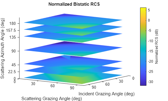
Plot the in-plane and out-of-plane models. For the out-of-plane model, display azimuths of 0, 22.5, 45, 90, 135, 157.5, and 180 degrees.

plot(brefl,"InPlane")

Figure contains an axes object. The axes object with title In-Plane Normalized Bistatic RCS, xlabel In-Plane Scattering Angle (deg), ylabel Incident Grazing Angle (deg) contains 5 objects of type image, line, constantline, text. These objects represent Monostatic Geometry, Surface Normal.

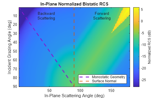
plot(brefl,Azimuth=[0 22.5 45 90 135 157.5 180])

Figure contains an axes object. The axes object with title Normalized Bistatic RCS, xlabel Incident Grazing Angle (deg), ylabel Scattering Grazing Angle (deg) contains 7 objects of type surface.

Define a custom function called in_plane_bartonFarm and use a gamma value of -15 dB at 10 GHz for reference. This value is taken from the surfaceReflectivityLand "Barton" Model "Farm" LandType. The custom function converts the gamma value to linear units and adds a frequency dependence. Then it uses bsxfun to modify the gamma value based on the bistatic geometry. [1] suggests that you can use the geometric mean of the monostatic normalized radar cross section (RCS) to generate a custom in-plane normalized bistatic RCS model for backscattering bistatic geometries.

function nbrcs = in_plane_bartonFarm(angIn,angScat,freq)
    inOutAngles = [angIn, angScat];
    gammaCdB = -15; 
    gammaCdB = gammaCdB + 5*log10(freq./10e9);
    gammaC = db2pow(gammaCdB); 
    nbrcs = bsxfun(@times,gammaC,sqrt(prod(sind(inOutAngles),2))); 
end

Create a bistaticSurfaceReflectiivityLand object and set the custom in-plane function handle to @in_plane_bartonFarm.

bref = bistaticSurfaceReflectivityLand(InPlaneModel="Custom",...
       CustomInPlaneFcn=@in_plane_bartonFarm)
bref = 
  bistaticSurfaceReflectivityLand with properties:

        InPlaneModel: 'Custom'
    CustomInPlaneFcn: @in_plane_bartonFarm
     OutOfPlaneModel: 'RuralInterpolation'
             Speckle: 'None'

Plot in-plane NBRCS values at 20 GHz.

bref.plot("InPlane",Frequency=20e9)

Figure contains an axes object. The axes object with title In-Plane Normalized Bistatic RCS, xlabel In-Plane Scattering Angle (deg), ylabel Incident Grazing Angle (deg) contains 5 objects of type image, line, constantline, text. These objects represent Monostatic Geometry, Surface Normal.

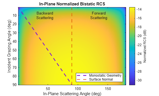
Return NBRCS values at specified bistatic configurations and frequencies.

nbrcs=bref([45;40],45,180,[20e9 21e9])
nbrcs = 2×2

    0.0319    0.0327
    0.0304    0.0311

[1] Barton, David K. "Land Clutter Models for Radar Design and Analysis." Proceedings of the IEEE 73, no. 2 (1985): 198-204.

More About

expand all

References

[1] A. R. Domville. "The Bistatic Reflection From Land and Sea of X-Band Radio Waves, Part I." GEC (Electronics) Ltd., Stanmore, England, Memorandum SLM1802 (1967).

[2] A. R. Domville. "The Bistatic Reflection From Land and Sea of X-Band Radio Waves, Part II." GEC (Electronics) Ltd., Stanmore, England, Memorandum SLM2116 (1968).

[3] C. Maitland et al. "Development of a Bistatic Clutter Tool and Validation by Experimental Data," International Conference on Radar Systems, Hybrid Conference, Edinburgh, UK (2022): 125-129, doi: 10.1049/icp.2022.2303.

Extended Capabilities

expand all

C/C++ Code Generation
Generate C and C++ code using MATLAB® Coder™.

Version History

Introduced in R2026a