segmentGroundSMRF
Segment ground from lidar data using a SMRF algorithm
Syntax
Description
groundPtsIdx = segmentGroundSMRF(ptCloud)ptCloud into ground and nonground points
using a simple morphological filter (SMRF) algorithm. For more information on the SMRF
algorithm, see Simple Morphological Filter.
groundPtsIdx = segmentGroundSMRF(ptCloud,gridResolution)
[
returns the ground points and nonground points as individual groundPtsIdx,nonGroundPtCloud,groundPtCloud] = segmentGroundSMRF(___)pointCloud
objects, in addition to the ground point indices, using any of the input argument
combinations from previous syntaxes.
[___] = segmentGroundSMRF(___,
specifies options using one or more name-value arguments. For example,
Name=Value)ElevationThreshold=0.4 sets the elevation threshold for identifying
nonground points to 0.4.
Examples
Segment the ground in an unorganized aerial point cloud.
Create a lasFileReader object to access the data of aerialLidarData2.las.
fileName = fullfile(toolboxdir("lidar"),"lidardata","las", ...
           "aerialLidarData2.las");
lasReader = lasFileReader(fileName);
Read the point cloud data from the LAS file using the readPointCloud function.
ptCloud = readPointCloud(lasReader);
Segment the ground data from the point cloud.
[groundPtsIdx,nonGroundPtCloud,groundPtCloud] = segmentGroundSMRF(ptCloud);
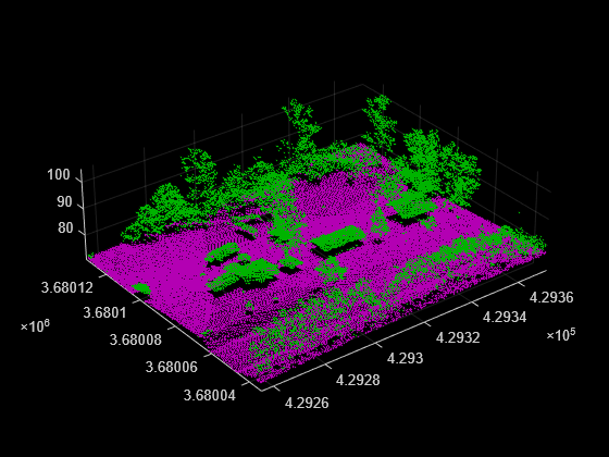
Visualize the ground and nonground points.
figure
pcshowpair(groundPtCloud,nonGroundPtCloud)
Segment and remove the ground from an organized point cloud.
Load the point cloud data into the workspace. This point cloud was captured in a highway scenario.
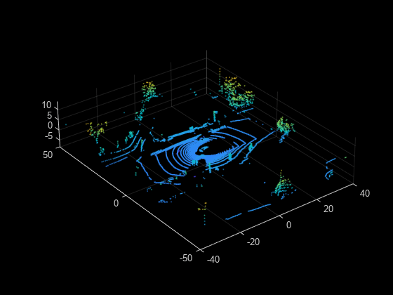
ld = load("drivingLidarPoints.mat");Display the input point cloud.
pcshow(ld.ptCloud)
xlim([-40 40])
ylim([-50 50])
Segment the ground data from the point cloud.
[~,nonGroundPtCloud,groundPtCloud] = segmentGroundSMRF( ...
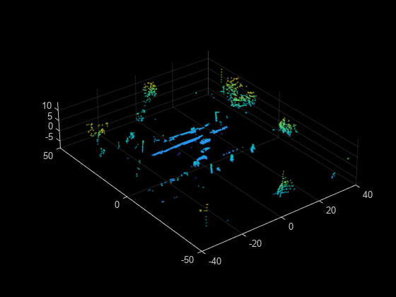
ld.ptCloud,MaxWindowRadius=5,ElevationThreshold=0.1,ElevationScale=0.25);Visualize the nonground points.
figure
pcshow(nonGroundPtCloud)
xlim([-40 40])
ylim([-50 50])
Input Arguments
Name-Value Arguments
Output Arguments
Algorithms
A simple morphological filter (SMRF) algorithm [1] segments point cloud data into ground and nonground points. The algorithm consists of three stages:
Create a minimum elevation surface map from the point cloud data.
Segment the surface map into ground and nonground grid elements.
Segment the original point cloud data.
Create Minimum Elevation Surface Map
Divide the point cloud data into grids along the xy- plane (bird's-eye view). Specify the grid size using
gridResolution.Find the lowest elevation (Zmin) value for each grid element (pixel).
Combine all the Zmin values into a 2-D matrix (raster image) to create a minimum elevation surface map.
Segment Surface Map
Apply a morphological opening operation on the minimum surface map. This applies an erosion filter followed by a dilation filter. For more information on morphological opening, see Types of Morphological Operations.
The shape of the structuring element and its window radius define the search neighborhood for the morphological opening. Use a disc-shaped structuring element, and start with a window radius of 1 pixel. For more information, see Structuring Elements.
Calculate the slope between the minimum surface and opened surface maps at each grid element. If the difference is greater than the elevation threshold, classify the pixel as nonground.
Execute steps 1 through 3 iteratively. Increase the window radius by 1 pixel in each iteration until it reaches the maximum radius specified by
MaxWindowRadius.The end result of the iteration process is a binary mask in which each pixel of the point cloud is classified as either ground or nonground.
Segment Original Point Cloud
Apply the binary mask to the original minimum surface map to remove nonground grids.
Fill the unfilled grids using image interpolation techniques to create an estimated elevation model.
Calculate the elevation difference between each point in the original point cloud and the corresponding point in the estimated elevation model. If the difference is greater than
ElevationThreshold, classify the pixel as nonground.Multiply the slope of the elevation model at the each point by
ElevationScale, and add the result to theElevationThresholdvalue to identify ground points on steep slopes.
References
[1] Pingel, Thomas J., Keith C. Clarke, and William A. McBride. “An Improved Simple Morphological Filter for the Terrain Classification of Airborne LIDAR Data.” ISPRS Journal of Photogrammetry and Remote Sensing 77 (March 2013): 21–30. https://doi.org/10.1016/j.isprsjprs.2012.12.002.
Extended Capabilities
Version History
Introduced in R2021a