このページの内容は最新ではありません。最新版の英語を参照するには、ここをクリックします。
作動
このセクションでは、複数の Simscape Fluids ドメインにおける作動システムの例を確認できます。
注目の例

拮抗する McKibben 型筋肉アクチュエータ
このデモでは、拮抗する接続関係の 2 つの空気筋肉アクチュエータ (または McKibben 型人工筋肉) に基づく筋肉作動を示します。空気筋肉アクチュエータはレバーの反対側に接続されています。4 方向バルブは電気機械バルブ アクチュエータによって制御されます。4 方向バルブで、高圧経路 P-A と戻りライン B-T が開いている場合、上部の空気筋肉アクチュエータは収縮し、反対側にある下部の空気筋肉アクチュエータを強制的に伸ばします。同様に、高圧経路 P-B と戻りライン A-T が開くと、下部の空気筋肉アクチュエータが収縮し始め、上部の空気筋肉アクチュエータを強制的に伸ばします。筋肉の振動運動は、スライダークランクでモデル化された機械的リンク機構に接続されている出力負荷の角回転に変換されます。

閉回路油圧アクチュエータ
この例では、可変速ポンプによって駆動される閉回路油圧アクチュエータを説明します。このアクチュエータは、2 つの補充バルブ (チェック バルブ) および補充タンクとして機能する 1 つのバネ式アキュムレータを備えた閉流体システムとして配置されています。ポンプ速度は、ピストンの指令位置と測定位置の差によって制御されます。アクチュエータは、バネ、ダンパー、および時変負荷に対して動作します。
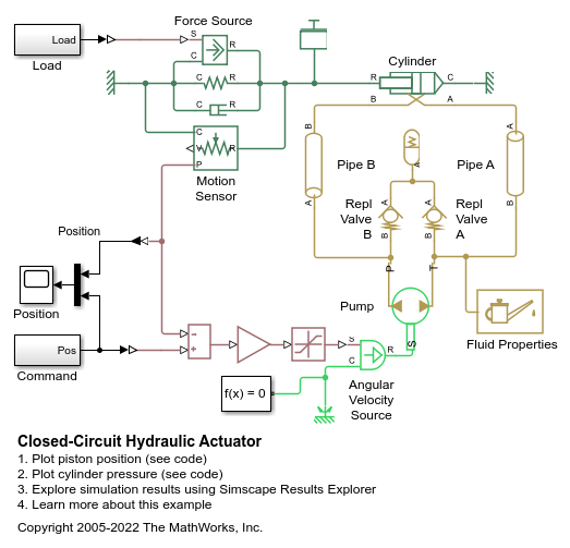
閉回路油圧アクチュエータ
警告: この例では油圧ドメインが使用されていますが、これは将来のリリースで削除される予定です。等温液体ドメインを使用する同等のモデル例を、閉回路油圧アクチュエータから見つけてください。等温流体ドメインにモデルを変換するには、hydraulicToIsothermalLiquid ツールを使用します。

Hydraulic Actuator with Counterbalance Valve
The model demonstrates extension, retraction, and holding of a hydraulic actuator with a counterbalance valve. An open-center 4-way directional valve controls a double-acting actuator, and a constant flow rate source equipped with a pressure relief valve serves as the power unit. The actuator is subject to an external force that tries to extend the actuator. The counterbalance valve modulates the return flow into port L, preventing the loss of control of the actuator in extending, as well as holding the piston in place at the neutral position of the valve. Port A of the actuator connects to port P of the counterbalance valve, making it impossible for the cylinder to move until the pressure at port A builds up to a certain level.

デュアル カウンターバランス バルブを備えた油圧アクチュエータ
この例では、4 方向バルブで制御されるアクチュエータに支配的な負荷がかかる場合を示しています。このような場合、方向制御バルブが中立位置にあるときは、カウンターバランス バルブを使用して負荷によるクリープを防ぐ必要があります。中立位置では、方向制御バルブは圧力端子 P をブロックしながら端子 A と端子 B をタンクに接続します。カウンターバランス バルブは流れがタンクに戻るのを防ぐため、アクチュエータは所定の位置に保たれます。

Hydraulic Actuator with Dual Counterbalance Valves
Warning: This example uses the hydraulic domain, which will be removed in a future release. Find an equivalent example model that uses the isothermal liquid domain here: デュアル カウンターバランス バルブを備えた油圧アクチュエータ. To convert models to the isothermal liquid domain, use the hydraulicToIsothermalLiquid tool.

Hydraulic Actuator with Telescopic Cylinder
Demonstrates the extension and retraction of a telescopic hydraulic actuator with three stages. The telescopic actuator extends and retracts one stage at a time.

Hydraulic Cylinder with Cylinder Cushions
A hydraulic double-acting actuator equipped with cushions on both end stops. The cushions serve as hydraulic brakes when the piston approaches the stops, absorbing some of the kinetic energy of the system before the piston touches the stops. For more information, see Double-Acting Actuator (IL).

Injection Molding Actuation System
An injection molding actuation system. The model contains a set of cartridge valves that control pumps, motors, and cylinders to execute the steps of an injection molding process.

圧力制御ソレノイド
この例では、圧力制御ソレノイド バルブをモデル化、パラメーター化、およびテストする方法を示します。この例では、加えられるソレノイド力と結果として生じるアクチュエータ端子圧力の関係を示すプロットも生成します。

差動シリンダーを備えた往復アクチュエータ
この例では、差動シリンダーを備えた複動式アクチュエータを示します。アクチュエータのシリンダー B にはポンプの出力が接続されているのに対し、アクチュエータのシリンダー A は 3 方向バルブを介してポンプまたはタンクのいずれかに接続されます。シリンダー A がポンプに接続されているときは、両方のシリンダーの圧力が等しくなります。シリンダー A の方が有効なピストン面積が大きいため、シリンダー A はシリンダー B よりも界面力が大きく、それによってピストンが伸びます。シリンダー A がタンクに接続されると、ピストンは後退を始めます。アクチュエータにおける繰り返しの往復運動を実現するために、正弦波信号で 3 方向バルブが制御されます。

Rotating Hydraulic Actuator
Uses a Rotating Single-Acting Actuator (IL) block to model a hydraulic cylinder actuator for operating friction clutches, brakes, and other devices installed on rotating shafts. A key element of the actuator is a piston that moves back and forth under an axial force that consists of the static pressure force and a rotating cylinder force developed by centrifugal force on the rotating fluid.

Secondary Cylinder
Model, parameterize and, test a secondary cylinder. Given the numerical data extracted from the datasheet of the single-stage primary cylinder, the unknown parameters of the secondary cylinder are calculated. The model is simulated to generate the plot between the applied force to the single-stage primary cylinder and the pressure developed inside the secondary cylinder.
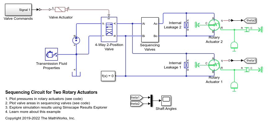
Sequencing Circuit for Two Rotary Actuators
A sequencing circuit that is based on four check valves installed in the pressure and return lines of the second rotary actuator. The cracking pressure of the meter-in check valves is set high enough to prevent flow into rotary actuator 2 while rotary actuator 1 is rotating, but lower than the pressure that develops once rotary actuator 1 reaches its hard stop. As a result, rotary actuator 2 starts moving only after rotary actuator 1 completes its stroke.

Sequencing Circuit for Two Rotary Actuators
Warning: This example uses the hydraulic domain, which will be removed in a future release. Find an equivalent example model that uses the isothermal liquid domain here: Sequencing Circuit for Two Rotary Actuators. To convert models to the isothermal liquid domain, use the hydraulicToIsothermalLiquid tool.

Single-Acting Cylinder with 3-Way Valve
A single-acting hydraulic cylinder controlled by a 3-way directional valve. The mass, viscous friction, and preloaded spring blocks represent the load. The pump is powerful enough to maintain constant pressure at the valve inlet. The signal from a Multiposition Valve Actuator block (Valve Actuator) controls the spool position of a 3-Way Directional Valve (IL) block (3-Way Valve).

Single-Stage Primary Cylinder
Model, parameterize, and test a single-stage primary cylinder starting from manufacturer datasheet information. Given the numerical data extracted from the datasheet, the unknown parameters are calculated. The model is then simulated and the resulting push rod force versus pressure relationship curve is compared with curve provided on the manufacturer datasheet.

Tandem Primary Cylinder
Model, parameterize and test a tandem primary cylinder starting from manufacturer datasheet information. First, there is a brief discussion on the mathematical modeling of the system. Given the numerical data extracted from the datasheet, optimization is then used to determine remaining unknown parameters. The model is then simulated and the resulting push rod force - brake pressure relationship curve is compared with the curve provided on the manufacturer datasheet. Understanding the behavior of the tandem primary cylinder is an important prerequisite to selection of other braking system components.