Main Content

dsphdl.FIRFilter

Finite-impulse response filter

Description

The dsphdl.FIRFilter System object™ models finite-impulse response filter architectures optimized for HDL code generation. The object accepts scalar or vector input, supports multichannel input, and provides an option for programmable coefficients by using a parallel interface or a memory interface. It provides a hardware-friendly interface with input and output control signals. To provide a cycle-accurate simulation of the generated HDL code, the object models architectural latency including pipeline registers and resource sharing.

The object provides three filter structures.

  • The direct form systolic architecture provides a fully parallel implementation that makes efficient use of Intel® and Xilinx® DSP blocks.

  • The direct form transposed architecture is a fully parallel implementation and is suitable for FPGA and ASIC applications.

  • The partly serial systolic architecture provides a configurable serial implementation that makes efficient use of FPGA DSP blocks.

For a filter implementation that matches multipliers, pipeline registers, and pre-adders to the DSP configuration of your FPGA vendor, specify your target device when you generate HDL code.

All single-channel filter structures remove multipliers for zero-valued coefficients, such as in half-band filters and Hilbert transforms. The object also provides an option to implement +/- 1 and power of 2 coefficients without a multiplier, and an option to implement all coefficients with CSD or factored-CSD logic. When you use scalar or multichannel input data, the filter shares multipliers for symmetric and antisymmetric coefficients. Frame-based filters do not implement symmetry optimization. Multichannel filters do not remove multipliers for zero-valued coefficients. Multichannel filters share resources between channels, even if the filter coefficients are different across the channels.

The latency between valid input data and the corresponding valid output data depends on the filter structure, serialization options, the number of coefficients, and whether the coefficient values provide optimization opportunities. For details of structure and latency, see FIR Filter Architectures for FPGAs and ASICs.

To filter input data with an HDL-optimized FIR filter:

  1. Create the dsphdl.FIRFilter object and set its properties.

  2. Call the object with arguments, as if it were a function.

To learn more about how System objects work, see What Are System Objects?

Creation

Description

firFilt = dsphdl.FIRFilter creates an HDL-optimized discrete FIR filter System object, firFilt, with default properties.

example

firFilt = dsphdl.FIRFilter(num) creates a filter with the Numerator property set to num.

firFilt = dsphdl.FIRFilter(___,Name=Value) sets properties using one or more name-value arguments.

For example:

Numerator = firpm(10,[0,0.1,0.5,1],[1,1,0,0]);
fir = dsphdl.FIRFilter(Numerator,FilterStructure='Direct form transposed');
...
[dataOut,validOut] = fir(dataIn,validIn);

Properties

expand all

Unless otherwise indicated, properties are nontunable, which means you cannot change their values after calling the object. Objects lock when you call them, and the release function unlocks them.

If a property is tunable, you can change its value at any time.

For more information on changing property values, see System Design in MATLAB Using System Objects.

Main

You can enter constant filter coefficients as a property, provide time-varying filter coefficients using an input argument, or provide time-varying filter coefficients using a memory-style interface.

You cannot use programmable coefficients with multichannel data.

When you select 'Input port (Parallel interface)', the object has the coeff argument.

When you select 'Input port (Memory interface)', the object has a memory-style interface with the coeff, caddr, cwren, and cdone arguments.

Setting this property to 'Input port (Parallel interface)' or 'Input port (Memory interface)' enables the NumeratorPrototype property. Specify a prototype to enable the object to optimize the filter implementation according to the values of the coefficients.

When you use programmable coefficients with frame-based input, the object does not optimize the filter for coefficient symmetry. Also, the output after a change of coefficient values might not match the output in the scalar case exactly. This difference occurs because the subfilter calculations are performed at different times relative to the input coefficient values, compared with the scalar implementation.

Dependencies

Before R2023b: To use 'Input port (Parallel interface)', set the FilterStructure property to 'Direct form systolic' or 'Direct form transposed'.

Discrete FIR filter coefficients, specified as a row vector of real or complex values. You can specify multichannel coefficients with a K-by-L matrix of real or complex values, where K is the number of channels and L is the filter length. To enable symmetry optimization, the symmetry characteristics of all channels must align. For example, if one channel is even-symmetric, all channels must be even-symmetric.

You can also specify the vector as a workspace variable, or as a call to a filter design function. When the input data type is a floating-point type, the object casts the coefficients to the same data type as the input. When the input data type is an integer type or a fixed-point type, you can set the coefficient data type by using the CoefficientsDataType property.

Example: dsphdl.FIRFilter('Numerator',firpm(30,[0 0.1 0.2 0.5]*2,[1 1 0 0])) defines coefficients using a linear-phase filter design function.

Dependencies

To enable this property, set NumeratorSource to 'Property'.

Prototype filter coefficients, specified as a vector of real or complex values. The prototype specifies a sample coefficient vector that is representative of the symmetry and zero-value locations of the expected input coefficients. If all input coefficient vectors have the same symmetry and zero-value coefficient locations, set NumeratorPrototype to one of those vectors. The object uses the prototype to optimize the filter by sharing multipliers for symmetric or antisymmetric coefficients and by removing multipliers for zero-value coefficients.

When you use frame-based input data, the object does not optimize the filter for coefficient symmetry. The object still uses the NumeratorPrototype property to remove multipliers for zero-valued coefficients.

NumeratorSourceInput SizeIf No Prototype
'Input port (Parallel interface)'

When you use scalar input data, coefficient optimizations affect the expected size of the vector in the coeff argument. Provide only the nonduplicate coefficients as the argument. For example, if you set the NumeratorPrototype property to a symmetric 14-tap filter, the block shares one multiplier between each pair of duplicate coefficients, so the block expects a vector of 7 values in the coeff argument. You must still provide zeros in the input coeff vector for the nonduplicate zero-valued coefficients.

When you use frame-based input data, specify a coeff vector that is the same size as the prototype.

If your coefficients are unknown or not expected to share symmetry or zero-valued locations, you can set the NumeratorPrototype property to [].

'Input port (Memory interface)'

Write the same number of coefficient values as the size of the prototype.

The NumeratorPrototype property cannot be empty. The object uses the prototype to determine the size of the coefficient memory. If your coefficients are unknown or not expected to share symmetry or zero-valued locations, set NumeratorPrototype to a vector with the same length as your expected coefficients, which does not contain symmetry or zero values, for example [1:1:NumCoeffs].

Dependencies

To enable this property, set NumeratorSource to 'Input port (Parallel interface)' or 'Input port (Memory interface)'.

HDL filter architecture, specified as one of these structures:

  • 'Direct form systolic' — This architecture provides a fully parallel filter implementation that makes efficient use of Intel and Xilinx DSP blocks. For architecture details, see Fully Parallel Systolic Architecture. When you specify multichannel coefficients with this architecture (with interleaved input samples), the object interleaves the channel coefficients over a single parallel filter.

  • 'Direct form transposed' — This architecture is a fully parallel implementation that is suitable for FPGA and ASIC applications. For architecture details, see Fully Parallel Transposed Architecture. When you specify multichannel coefficients with this architecture (with interleaved input samples), the object interleaves the channel coefficients over a single parallel filter.

  • 'Partly serial systolic' — This architecture provides a serial filter implementation and options for tradeoffs between throughput and resource utilization. The architecture makes efficient use of Intel and Xilinx DSP blocks. The object implements a serial L-coefficient filter with M multipliers and requires input samples that are at least N cycles apart, such that L = N×M. You can specify either M or N. For this implementation, the object provides the ready output argument which indicates when the object is ready for new input data. For architecture and performance details, see Partly Serial Systolic Architecture (1 < N < L) and Fully Serial Systolic Architecture (N ≥ L). You cannot use frame-based input with the partly serial architecture.

    When you specify multichannel coefficients with a serial architecture, you must specify the serialization factor as the number of cycles between valid input samples.

    For multichannel input that is scalar and interleaved over the channels, the object implements these serial architectures:

    • When N < L: Partly serial filter with L/N multipliers.

    • When N >= L: Fully serial filter.

    When your multichannel input is a 1-by-K vector, where K is the number of channels, the object implements these serial architectures:

    • When N = 1: Filter bank of fully parallel filters.

    • When 1 < N < K: Filter bank of partly serial filters. (since R2024a)

    • When N = K: Fully parallel filter with channel coefficients interleaved.

    • When K < N < L×K: Partly serial filter with L×K/N multipliers.

    • When N >= L×K: Fully serial filter.

If any filter is symmetric, the architecture shares multipliers for matching coefficients, so effectively L becomes L/2. To enable the symmetry optimization for multichannel filters, the symmetry characteristics of all channels must align.

All single-channel implementations remove multipliers for zero-valued coefficients. Multichannel filters do not optimize for zero-valued coefficients. When you use scalar or multichannel input data, the filter shares multipliers for symmetric and antisymmetric coefficients. Frame-based filters do not implement symmetry optimization. Multichannel filters share resources between channels, even if the filter coefficients are different across the channels.

Specify the rule that the object uses to serialize the filter as either:

  • 'Minimum number of cycles between valid input samples' — Specify a requirement for input data timing by using the NumCycles property.

  • 'Maximum number of multipliers' — Specify a requirement for resource usage by using the NumberOfMultipliers property. This option is not supported when you have multichannel coefficients.

For a filter with L coefficients, the object implements a serial filter with not more than M multipliers and requires input samples that are at least N cycles apart, such that L = N×M. The object might remove additional multipliers when it applies coefficient optimizations, so the actual M or N values of the filter implementation might be lower than the specified value.

If the filter is symmetric, the architecture shares multipliers for matching coefficients, so effectively L = L/2.

When you use complex input data and/or complex coefficients with a single-channel partly serial architecture, the object implements complex interleaving to share the multipliers over inactive input cycles. For complex input and complex coefficients, the object needs at least L×3 cycles to implement the filter with a single multiplier. For complex input with real coefficients or complex coefficients with real input, the object needs at least L×2 cycles to implement the filter with a single multiplier. (since R2023b)

Dependencies

To enable this property, set FilterStructure to 'Partly serial systolic'.

Serialization requirement for input timing, specified as a positive integer. This property represents N, the minimum number of cycles between valid input samples. In this case, the object calculates M = L/N. To implement a fully serial architecture, set NumCycles to a value greater than the filter length, L, or to Inf. To implement a fully serial architecture for a multichannel filter with 1-by-K vector input, set NumCycles to a value greater than L×K, where K is the number of channels.

To implement a fully serial architecture for a single channel filter with complex input and complex coefficients, set NumCycles greater than L×3. If you have complex input with real coefficients or complex coefficients with real input, set NumCycles greater than L×2.

If the filter is symmetric, the architecture shares multipliers for matching coefficients, so effectively L = L/2.

The object might remove multipliers when it applies coefficient optimizations, so the actual M and N values of the filter might be lower than the specified value.

Dependencies

To enable this property, set FilterStructure to 'Partly serial systolic' and set SerializationOption to 'Minimum number of cycles between valid input samples'.

Serialization requirement for resource usage, specified as a positive integer. This property represents M, the maximum number of multipliers in the filter implementation. In this case, the object calculates N = L/M. If the input data is complex, the object allocates floor(M/2) multipliers for the real part of the filter and floor(M/2) multipliers for the imaginary part of the filter. To implement a fully serial architecture, set NumberOfMultipliers to 1 for real input with real coefficients, 2 for complex input and real coefficients or real coefficients with complex input, or 3 for complex input and complex coefficients.

If the filter is symmetric, the architecture shares multipliers for matching coefficients, so effectively L = L/2.

When you use complex input data and/or complex coefficients with a single-channel partly serial architecture, the object implements complex interleaving to share the multipliers over inactive input cycles. For complex input and complex coefficients, the object needs at least L×3 cycles to implement the filter with a single multiplier. For complex input with real coefficients or complex coefficients with real input, the object needs at least L×2 cycles to implement the filter with a single multiplier.

The object might remove multipliers when it applies coefficient optimizations, so the actual M and N values of the filter might be lower than the specified value.

Dependencies

To enable this property, set the FilterStructure to 'Partly serial systolic', and set SerializationOption to 'Maximum number of multipliers'.

You cannot use this property when you specify multichannel coefficients. Use the NumCycles property instead.

Data Types

Rounding method for type-casting the output, specified as 'Floor', 'Ceiling', 'Convergent', 'Nearest', 'Round', or 'Zero'. The rounding method is used when casting the output to the data type specified by the OutputDataType property. When the input data type is floating point, the object ignores the RoundingMethod property. For more details, see Rounding Modes.

Overflow handling for type-casting the output, specified as 'Wrap' or 'Saturate'. Overflow handling is used when casting the output to the data type specified by the OutputDataType property. When the input data type is floating point, the object ignores the OverflowAction property. For more details, see Overflow Handling.

Data type of discrete FIR filter coefficients, specified as 'Same word length as input' or a numerictype object. To specify a numerictype object, call numerictype(s,w,f), where:

  • s is 1 for signed and 0 for unsigned.

  • w is the word length in bits.

  • f is the number of fractional bits.

When the input is a fixed-point or integer type, the object casts the filter coefficients using the rule or data type in this property. The quantization rounds to the nearest representable value and saturates on overflow. When the input data type is floating point, the object ignores this property and all internal arithmetic uses the same data type as the input.

The recommended setting for this property is 'Same word length as input'.

The object returns a warning or error if:

  • The coefficients data type does not have enough fractional length to represent the coefficients accurately.

  • The coefficients data type is unsigned and the coefficients include negative values.

Dependencies

To enable this property, set NumeratorSource to 'Property'.

Data type of discrete FIR filter output, specified as 'Same word length as input', 'Full precision', or a numerictype object. To specify a numerictype object, call numerictype(s,w,f), where:

  • s is 1 for signed and 0 for unsigned.

  • w is the word length in bits.

  • f is the number of fractional bits.

When the input is a fixed-point or integer type, the object casts the output of the filter using the rule or data type in this property. The quantization uses the settings of the RoundingMethod and OverflowAction properties. When the input data type is floating point, the object ignores this parameter and returns output in the same data type as the input.

The object increases the word length for full precision inside each filter tap and casts the final output to the specified type. The maximum final internal data type (WF) depends on the input data type (WI), the coefficient data type (WC), and the number of coefficients (L), and is given by

WF = WI + WC + ceil(log2(L)).

When you specify a fixed set of coefficients, the actual full-precision internal word length is usually smaller than WF because the values of the coefficients limit the potential growth. When you use programmable coefficients, the object cannot calculate the dynamic range, and the internal data type is always WF.

Control Arguments

Option to enable the reset input argument, specified as true or false. When you set this property to true, the object expects a value for the reset input argument. The reset signal implements a local synchronous reset of the data path registers.

For more reset considerations, see the Reset Signal section on the Hardware Control Signals page.

Option to connect the data path registers to the generated HDL global reset signal, specified as true or false. Set this property to true to connect the generated HDL global reset signal to the data path registers. This property does not change the arguments of the object or modify simulation behavior in MATLAB®. When you set this property to false, the generated HDL global reset clears only the control path registers. The generated HDL global reset can be synchronous or asynchronous depending on your HDL code generation settings.

For more reset considerations, see the Reset Signal section on the Hardware Control Signals page.

Implementation

Since R2023b

By default, the object implements coefficient multipliers using a hardware multiplier. Select 'CSD/Factored-CSD' to replace coefficient multipliers with a CSD or factored-CSD implementation. A CSD or factored-CSD implementation uses shift and add operations rather than multipliers. When you select CSD, coefficients of +/- 1 and power of 2 are also implemented with shift logic.

The latency of the block does not change with multiplier implementation. Each multiplier has the same number of pipeline stages around it in either implementation

Dependencies

To enable this parameter, set FilterStructure property to 'Direct form transposed'. Using CSD multipliers with systolic architecture is not supported because it can prevent efficient use of FPGA DSP blocks.

CSD implementations are not supported for multichannel or programmable filters.

Since R2023b

By default, the object implements special-value coefficient multipliers using a hardware multiplier. Set this property to false to replace special-value coefficient multipliers with a shift implementation.

Dependencies

To enable this property, set the FilterStructure property to 'Direct form transposed', and set CoeffMultiplier to 'Multiplier', or set FilterStructure to 'Direct form systolic'.

CSD implementations are not supported for multichannel or programmable filters.

Since R2023b

This property is read-only.

The object uses this constant property when you set FilterStructure to 'Direct form systolic'. Using CSD multipliers with systolic architecture is not supported because it can prevent efficient use of FPGA DSP blocks.

Usage

Description

[dataOut,validOut] = firFilt(dataIn,validIn) filters the input data only when validIn is true.

[dataOut,validOut,ready] = firFilt(dataIn,validIn) returns ready set to true when the object is ready to accept new input data on the next call.

The object returns the ready argument only when you set the FilterStructure property to 'Partly serial systolic'. For example:

firFilt = dsphdl.FIRFilter(Numerator,...
            FilterStructure='Partly serial systolic',...
            SerializationOption='Minimum number of cycles between valid input samples',...
            NumCycles=8)
...
for k=1:length(dataIn)
    [dataOut,validOut,ready] = firFilt(dataIn(k),validIn(k));

[dataOut,validOut] = firFilt(dataIn,validIn,coeff) filters data using the coefficients coeff. Use this syntax when you set the NumeratorSource property to 'Input port (Parallel interface)'. For example:

firFilt = dsphdl.FIRFilter(NumeratorSource='Input Port (Parallel interface)')
Numerator = myGetNumerator();  % calculate coefficients
for k=1:length(dataIn)
    [dataOut(x),validOut(x++)] = firFilt(dataIn(k),validIn(k),Numerator);

[dataOut,validOut] = firFilt(dataIn,validIn,coeff,caddr,cwren,cdone) loads the coefficient value coeff to the caddr memory location, when cwren is 1 (true). Set cdone to 1 (true) after you finish writing coefficients. The object ignores any input data provided when cwren is 1 (true), but still returns dataOut with validOut until it clears the filter pipeline. Use this syntax when you set the NumeratorSource property to 'Input port (Memory interface)'. For example:

firFilt = dsphdl.FIRFilter(NumeratorSource='Input Port (Memory interface)')
...
for k=1:length(Numerator)
    [dataOut(x),validOut(x++)] = firFilt(0,0,Numerator(k),k,true,(k==length(Numerator));
for k=1:length(dataIn)
[dataOut(x),validOut(x++)] = firFilt(dataIn(k),validIn(k),0,0,false,false);

[dataOut,validOut] = firFilt(dataIn,validIn,reset) filters data when reset is false. When reset is true, the object resets the filter registers. The object expects the reset argument only when you set the ResetInputPort property to true. For example:

firFilt = dsphdl.FIRFilter(Numerator,ResetInputPort=true)
...
% reset the filter
firFilt(0,false,true);
for k=1:length(dataIn)
    [dataOut(x),validOut(x++)] = firFilt(dataIn(k),validIn(k),false);

For more reset considerations, see the Reset Signal section on the Hardware Control Signals page.

Input Arguments

expand all

Input data, specified as a scalar, column vector, or row vector of real or complex values. Use a column vector to increase throughput by processing samples in parallel.
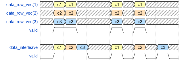
You can use a row vector to represent multiple channels, or you can provide scalar multichannel data with the channels interleaved. The channels can have independent filter coefficients. (since R2023a)

In R2023a and R2023b: you can use multichannel row-vector input only if there are at least as many invalid cycles between inputs as there are channels. When the input is a multichannel vector, the FilterStructure must be set to 'Partly serial systolic', and NumberOfCycles must be equal to or greater than the number of channels. This time allows the block to implement a partly-serial architecture that shares resources between the channels.

Frame based (column vector) input is not supported with multichannel coefficients.

The size of the row or column vector must be less than or equal to 64 elements. To implement a multichannel filter with more than 64 channels, you must use interleaved scalar input.

When the input data type is an integer type or a fixed-point type, the object uses fixed-point arithmetic for internal calculations and provides properties to customize the data types. When the input data type is a floating-point type, the object uses that input floating-point type for internal calculations and the output data type.

The software supports double and single data types for simulation, but not for HDL code generation.

Data Types: fi | single | double | int8 | int16 | int32 | uint8 | uint16 | uint32
Complex Number Support: Yes

Control signal that indicates if the input data is valid. When validIn is 1 (true), the object captures the values from the dataIn argument. When validIn is 0 (false), the object ignores the values from the dataIn argument.

Data Types: logical

Filter coefficients, specified as a vector of real or complex values. You can change the input coefficients at any time. When you use scalar input data, the size of the vector depends on the size and symmetry of the sample coefficients specified in the NumeratorPrototype property. The prototype specifies a sample coefficient vector that is representative of the symmetry and zero-value locations of the expected input coefficients. The object uses the prototype to optimize the filter by sharing multipliers for symmetric or antisymmetric coefficients, and by removing multipliers for zero-value coefficients. Therefore, provide only the nonduplicate coefficients in the argument. For example, if you set the NumeratorPrototype property to a symmetric 14-tap filter, the object expects a vector of 7 values for the coeff argument. You must still provide zeros in the input coeff vector for the nonduplicate zero-value coefficients.

When you use frame-based input data, the object does not optimize the filter for coefficient symmetry. The object still uses the NumeratorPrototype property to remove multipliers for zero-valued coefficients. Specify an input coeff vector that is the same size as the prototype.

If the input data is a fixed-point type, the coeff values must also be of a fixed point type. If the input data is a floating-point data type, the coeff values must be of the same data type.

The software supports double and single data types for simulation, but not for HDL code generation.

Dependencies

To enable this argument, set the NumeratorSource property to 'Input port (Parallel interface)'.

Data Types: fi | single | double | int8 | int16 | int32 | uint8 | uint16 | uint32

Since R2023a

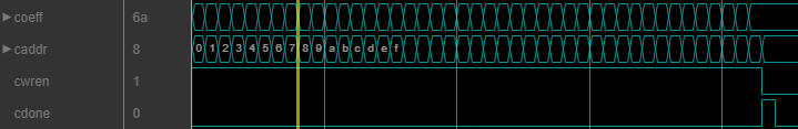
Filter coefficients, specified as a real or complex scalar value to write to internal memory. To load a single coefficient value to internal memory, specify a coeff value with a corresponding address in the caddr argument and an enable signal in the cwren argument. You can change the input coefficients at any time.

Waveform that shows writing a set of coefficients to the filter by using the memory interface

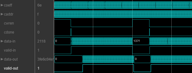
While you write new coefficients into memory, the object ignores any input data, but still returns dataOut with validOut until it clears the filter pipeline. The object resumes accepting input one cycle after cdone is set to 1 (true).

Waveform that shows the filter stops processing input data while receiving new coefficients on the memory interface

The coefficient memory has the same number of addresses as the size of the NumeratorPrototype property. The prototype specifies a sample coefficient vector that is representative of the symmetry and zero-valued locations of the expected input coefficients. When you use scalar input data, the object uses the prototype to optimize the filter by sharing multipliers for symmetric or antisymmetric coefficients, and by removing multipliers for zero-valued coefficients. You must write the entire set of coefficients to the memory, including symmetric or zero-value coefficients. For example, if you set the NumeratorPrototype property to a symmetric 14-tap filter, you must write 14 values to the memory interface.

When you use frame-based input data, the object does not optimize the filter for coefficient symmetry. The block still uses the NumeratorPrototype property to remove multipliers for zero-valued coefficients. The coefficient memory has the same number of locations as the size of the prototype.

If the input data is a fixed-point type, the coeff values must also be of a fixed point type. If the input data is a floating-point data type, the coeff values must be of the same data type.

The software supports double and single data types for simulation, but not for HDL code generation.

Dependencies

To enable this argument, set the NumeratorSource property to 'Input port (Memory interface)'.

Data Types: fi | single | double | int8 | int16 | int32 | uint8 | uint16 | uint32

Since R2023a

Specify the filter coefficient address as a scalar integer value represented as an unsigned fixed-point type with zero fractional bits. The object derives the size of this integer value, and the size of the internal memory, from the number of unique coefficients in the NumeratorPrototype property value.

The software supports double and single data types for simulation, but not for HDL code generation.

Dependencies

To enable this argument, set the NumeratorSource property to 'Input port (Memory interface)'.

Data Types: fi(0,N,0)

Since R2023a

Set this argument to 1 (true) to write the value of the coeff argument into the caddr location in internal memory.

The software supports double and single data types for simulation, but not for HDL code generation.

Dependencies

To enable this argument, set the NumeratorSource property to 'Input port (Memory interface)'.

Data Types: fi(0,N,0)

Since R2023a

Set this argument to 1 (true) to indicate that the current arguments write the final coefficient value to memory.

The software supports double and single data types for simulation, but not for HDL code generation.

Dependencies

To enable this argument, set the NumeratorSource property to 'Input port (Memory interface)'.

Data Types: fi(0,N,0)

Control signal that clears internal states. When reset is 1 (true), the object stops the current calculation and clears internal states. When the reset is 0 (false) and the input valid is 1 (true), the block captures data for processing.

For more reset considerations, see the Reset Signal section on the Hardware Control Signals page.

Dependencies

To enable this argument, set the ResetInputPort property to true.

Data Types: logical

Output Arguments

expand all

Filtered output data, returned as a scalar, column vector, or row vector of real or complex values. The dimensions of the output data match the dimensions of the input data. When the input data is floating point, the output data inherits the data type of the input data. When the input data is an integer type or fixed-point type, the OutputDataType property determines the output data type.

Data Types: fi | single | double | int8 | int16 | int32 | uint8 | uint16 | uint32
Complex Number Support: Yes

Control signal that indicates if the output data is valid. When validOut is 1 (true), the object returns valid data from the dataOut argument. When validOut is 0 (false), values from the dataOut argument are not valid.

Data Types: logical

Control signal that indicates that the object is ready for new input data sample on the next cycle. When ready is 1 (true), you can specify the dataIn and validIn inputs for the next time step. When ready is 0 (false), the object ignores any input data in the next time step.

When using the partly serial architecture, the object processes one sample at a time. If your design waits for the object to return ready set to 0 (false) before setting validIn to 0 (false), then one additional input data value arrives at the object. The object stores this additional data while processing the current data, and does not set ready to 1 (true) until the additional input is processed.

Dependencies

To enable this argument, set the FilterStructure property to 'Partly serial systolic'.

Data Types: logical

Object Functions

To use an object function, specify the System object as the first input argument. For example, to release system resources of a System object named obj, use this syntax:

release(obj)

expand all

getLatencyLatency of FIR filter
stepRun System object algorithm
releaseRelease resources and allow changes to System object property values and input characteristics
resetReset internal states of System object

Examples

collapse all

To generate HDL code from a System object™, create a function that contains and calls the object.

Create Function

Write a function that creates and calls an 11-tap HDL FIR filter System object. You can generate HDL code from this function.

function [dataOut,validOut] = HDLFIR11Tap(dataIn, validIn)
%HDLFIR11Tap
% Process one sample of data by using the dsphdl.FIRFilter System
% object. 
% dataIn is a fixed-point scalar value. 
% You can generate HDL code from this function.
    persistent fir
    if isempty(fir)
        Numerator = firpm(10,[0 0.1 0.5 1],[1 1 0 0]);
        fir = dsphdl.FIRFilter(Numerator);
    end
    [dataOut,validOut] = fir(dataIn,validIn);    
end

% Copyright 2017-2023 The MathWorks, Inc. 

Create Test Bench for Function

Clear the workspace, create an input signal of random noise, and allocate memory for outputs.

clear variables
clear HDLFIR11Tap
L = 200;
dataIn = fi(randn(L,1),1,16);
validIn = ones(L,1,'logical');
dataOut = fi(zeros(L,1),1,16);
validOut = false(L,1);

Call the function on the input signal.

for k = 1:L
    [dataOut(k),validOut(k)] = HDLFIR11Tap(dataIn(k), validIn(k));
end

Plot the signals with the Logic Analyzer.

la = dsp.LogicAnalyzer(NumInputPorts=4,SampleTime=1,TimeSpan=L);
tags = getDisplayChannelTags(la);
modifyDisplayChannel(la,tags{1},'Name','validIn');
modifyDisplayChannel(la,tags{2},'Name','dataIn');
modifyDisplayChannel(la,tags{3},'Name','dataOut');
modifyDisplayChannel(la,tags{4},'Name','validOut');
la(validIn,dataIn,dataOut,validOut)

This example shows how to configure the dsphdl.FIRFilter System object™ as a partly-serial 31-tap lowpass filter.

Design the filter coefficients. Then create an HDL FIR filter System object. Set the FilterStructure to 'Partly serial systolic'. By default, the SerializationOption property is 'Minimum number of cycles between valid input samples', and so you must specify the serialization rule using the NumCycles property. To share each multiplier between 10 coefficients, set the NumCycles to 10.

numerator = firpm(30,[0 0.1 0.2 0.5]*2,[1 1 0 0]);
numCycles = 10;
firFilt = dsphdl.FIRFilter(numerator, ...
    FilterStructure='Partly serial systolic', ...
    NumCycles=numCycles);

This serial filter implementation requires 10 time steps to calculate each output. Create input signals dataIn and validIn such that new data is applied only every NumCycles time steps.

L = 16;
x = fi(randn(L,1),1,16);
dataIn = zeros(L*numCycles,1,'like',x);
dataIn(1:numCycles:end) = x;
validIn = false(L*numCycles,1);
validIn(1:numCycles:end) = true;

Create a LogicAnalyzer object to view the inputs and output signals.

la = dsp.LogicAnalyzer(NumInputPorts=5, ...
    SampleTime=1, ...
    TimeSpan=length(dataIn));
tags = getDisplayChannelTags(la);
modifyDisplayChannel(la,tags{1},'Name','dataIn');
modifyDisplayChannel(la,tags{2},'Name','validIn');
modifyDisplayChannel(la,tags{3},'Name','dataOut');
modifyDisplayChannel(la,tags{4},'Name','validOut');
modifyDisplayChannel(la,tags{5},'Name','ready');

Call the filter System object on the input signals, and view the results in the Logic Analyzer. The object models HDL pipeline registers and resource sharing, so the waveform shows an initial delay before the object returns valid output samples.

for k=1:length(dataIn)
    [dataOut,validOut,ready] = firFilt(dataIn(k),validIn(k));
    la(dataIn(k),validIn(k),dataOut,validOut,ready)
end

The latency of the dsphdl.FIRFilter System object™ varies with filter structure, serialization options, input vector size, and whether the coefficient values provide optimization opportunities. Use the getLatency function to find the latency of a particular configuration. The latency is the number of cycles between the first valid input and the first valid output.

Create a dsphdl.FIRFilter System object™ and request the latency. The default architecture is fully parallel systolic. The default data type for the coefficients is 'Same word length as input'. Therefore, when you call the getLatency object function, you must specify an input data type. The object casts the coefficient values to the input data type, and then checks for symmetric coefficients. This Numerator has 31 symmetric coefficients, so the object optimizes for the shared coefficients, and implements 16 multipliers.

Numerator = firpm(30,[0 0.1 0.2 0.5]*2,[1 1 0 0]);
Input_type = numerictype(1,16,15); % object uses only the word length for coefficient type cast
hdlfir = dsphdl.FIRFilter(Numerator);
L_sysp = getLatency(hdlfir,Input_type)
L_sysp = 23

For the same fully parallel filter with vector input, the latency is lower. Call getLatency with an input vector size of four to check the latency for that case. The empty arguments are placeholders for when you use programmable coefficients or complex input data.

L_syspv = getLatency(hdlfir,Input_type,[],[],4)
L_syspv = 17

Check the latency for a partly serial systolic implementation of the same filter. By default, the SerializationOption property is 'Minimum number of cycles between valid input samples', and so you must specify the serialization rule using the NumCycles property. To share each multiplier between 8 coefficients, set the NumCycles to 8. The object then optimizes based on the coefficient symmetry, so there are 16 unique coefficients shared 8 times each over 2 multipliers. This serial filter implementation requires input samples that are valid every 8 cycles.

hdlfir = dsphdl.FIRFilter(Numerator,FilterStructure='Partly serial systolic', ...
                          NumCycles=8);
L_syss = getLatency(hdlfir,Input_type)
L_syss = 19

Check the latency of a nonsymmetric fully parallel systolic filter. The Numerator has 31 coefficients.

Numerator = sinc(0.4*[-30:0]);
hdlfir = dsphdl.FIRFilter(Numerator);
L_sysp = getLatency(hdlfir,Input_type)
L_sysp = 37

Check the latency of the same nonsymmetric filter implemented as a partly serial systolic filter. In this case, specify the SerializationOption by the number of multipliers. The object implements a filter that has 2 multipliers and requires 8 cycles between input samples.

hdlfir = dsphdl.FIRFilter(Numerator,FilterStructure='Partly serial systolic', ...
                          SerializationOption='Maximum number of multipliers', ...
                          NumberOfMultipliers=2);
L_syss = getLatency(hdlfir,Input_type)
L_syss = 37

Check the latency of a fully parallel transposed architecture. The latency for this filter structure with scalar input is always 6 cycles.

hdlfir = dsphdl.FIRFilter(Numerator,FilterStructure='Direct form transposed');
L_trans = getLatency(hdlfir,Input_type)
L_trans = 6

The latency of the transposed filter increases with input vector size.

L_transv4 = getLatency(hdlfir,Input_type,[],[],4)
L_transv4 = 9
L_transv8 = getLatency(hdlfir,Input_type,[],[],16)
L_transv8 = 11

Algorithms

This System object implements the algorithms described on the Discrete FIR Filter block reference page.

Extended Capabilities

Version History

Introduced in R2017a

expand all