信号処理モデル向け Simulink 環境の構成
DSP Simulink モデル テンプレートについて
DSP Simulink® モデル テンプレートを使用すると、デジタル信号処理モデリングの推奨設定で Simulink 環境を自動的に構成できます。DSP Simulink モデル テンプレートでは、コンフィギュレーション パラメーターを含む設定の再利用が可能です。ベスト プラクティスを使用するテンプレートからモデルを作成し、一般的な問題に対する以前のソリューションを活用できます。新規モデルで既定のキャンバスの代わりに、テンプレート モデルを選択してすぐに作業を開始できます。
Simulink モデル テンプレートの詳細については、モデルからのテンプレートの作成 (Simulink)を参照してください。
DSP System Toolbox の Simulink モデル テンプレートを使用したモデルの作成
新しい空のモデルを作成し、ライブラリ ブラウザーを開くには、次のようにします。
MATLAB® [ホーム] タブの [ファイル] セクションで、[新規]、[Simulink モデル] をクリックします。組み込みの Simulink モデル テンプレートと共に Simulink のスタート ページが開きます。
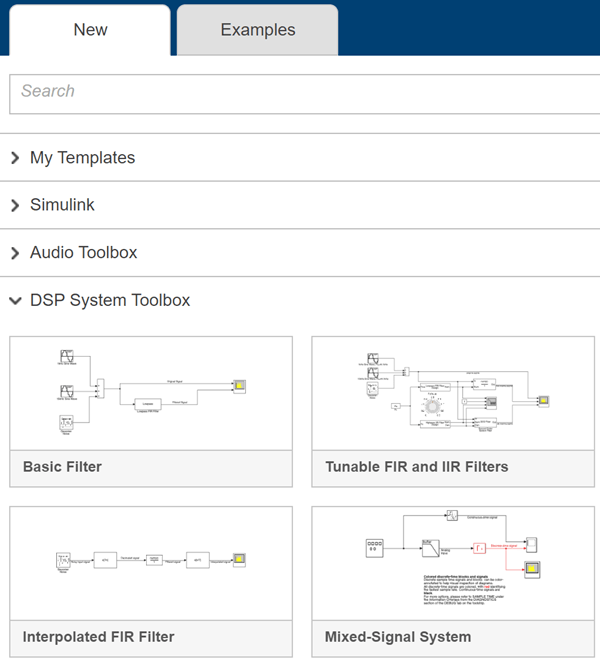
[DSP System Toolbox] でいずれかのテンプレートをクリックし、DSP System Toolbox™ での使用に適した設定でモデルを作成します。テンプレートの設定とコンテンツを使用した新規モデルが Simulink エディターに表示されます。モデルは、保存するまでメモリ内にのみ存在します。
ライブラリ ブラウザーにアクセスするには、モデルのツールストリップの [ライブラリ ブラウザー] をクリックします。
DSP Simulink モデル テンプレート
DSP Simulink モデル テンプレートのいずれかを選択してモデルを作成すると、モデルは DSP System Toolbox の推奨設定を使用するように構成されます。この表はそれらの設定の一部を示しています。
| コンフィギュレーション パラメーター | 設定 |
|---|---|
| SingleTaskRateTransMsg | error |
| multiTaskRateTransMsg | error |
| Solver | fixedstepdiscrete |
| EnableMultiTasking | オフ |
| StartTime | 0.0 |
| StopTime | inf |
| FixedStep | auto |
| SaveTime | off |
| SaveOutput | off |
| AlgebraicLoopMsg | error |
| SignalLogging | off |
| FrameProcessingCompatibilityMsg | error |
DSP System Toolbox の Simulink モデル テンプレートを以下に示します。
基本フィルター
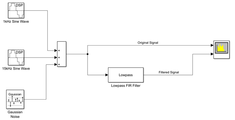
[基本フィルター] をクリックして、DSP System Toolbox 用の推奨設定で構成された基本フィルター モデルを作成します。
このモデルは、ローパス フィルターを実装しており、フィルター処理された信号を元の信号と比較できます。モデルは、Simulink 内で、DSP System Toolbox を使用したフィルター処理アルゴリズムのモデル化の開始点として機能します。
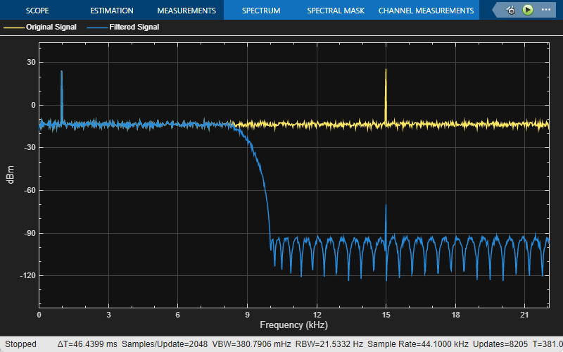
以下は元の信号とフィルター処理された信号を示すスペクトル アナライザーの出力です。入力信号は 1 kHz と 15 kHz のトーンを含みます。1 kHz のトーンはフィルター処理された出力で渡され、15 kHz のトーンは減衰されます。
調整可能な FIR および IIR フィルター
[調整可能な FIR および IIR フィルター] テンプレートを使用して、調整可能なフィルター仕様で FIR および IIR フィルターの設計と実装を行います。
このモデルは、Lowpass FIR Filter Design および Lowpass IIR Filter Design 設計ブロックを使用して FIR および IIR フィルターを設計する方法を示しています。Knob (Simulink) ブロックを使用してフィルターのカットオフ周波数を調整できます。シミュレーション中にフィルターのカットオフ周波数を調整すると、設計したフィルターの振幅応答が変化します。Filter Visualizer ブロックを使用して、設計したフィルターの振幅応答を可視化します。基本フィルターのモデル テンプレートと同様に、入力は 1 kHz と 15 kHz のトーンおよびノイズを含む正弦波信号です。
Discrete FIR Filter (Simulink) ブロックおよび Second-Order Section Filter ブロックは、設計ブロックからの係数を使用してローパス FIR フィルターおよびハイパス IIR フィルターを実装します。
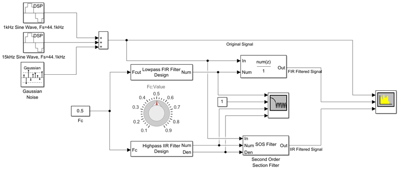
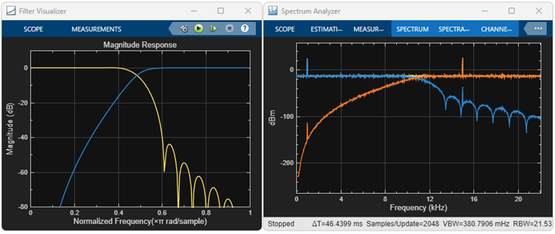
フィルター ビジュアライザーの出力は FIR フィルターと IIR フィルターの振幅応答の変化を示し、スペクトル アナライザーの出力は元の信号とフィルター処理された信号のスペクトルを示します。スペクトル アナライザーの出力では、両方のトーンが減衰されます。1 kHz のトーンは IIR フィルターによって減衰され、15 kHz のトーンは FIR フィルターによって減衰されます。
内挿 FIR フィルター
[内挿 FIR フィルター] テンプレートは、より低いサンプル レートで信号をフィルター処理するため、単一ステージ高次 FIR フィルターの効率的な代替手段となります。この内挿は、入力信号を複数のステージで処理します。ノイズを含む入力は、最初に FIR 間引きを通過します。これにより信号のサンプル レートが低下します。次に、この低下したサンプル レートで FIR フィルターによって信号がフィルター処理されます。終端の FIR 内挿器は、フィルター処理された出力のサンプル レートを変換して元の値に戻します。
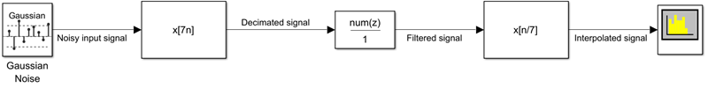
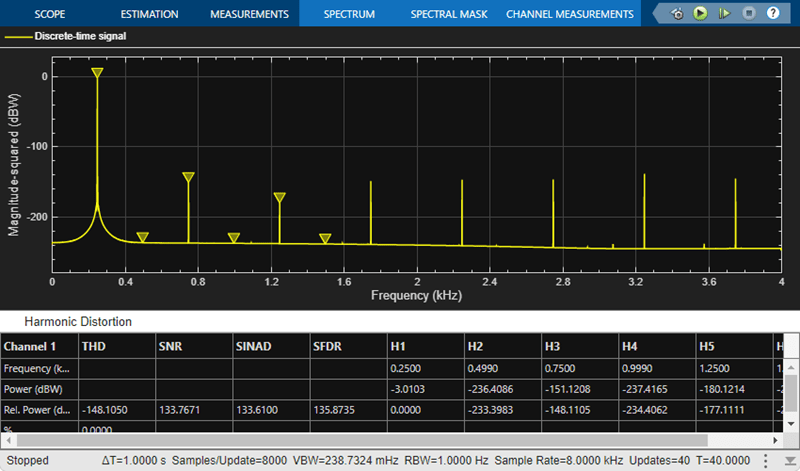
モデル内の Spectrum Analyzer ブロックは、フィルター処理された信号のスペクトルを示します。

ミックスドシグナル システム
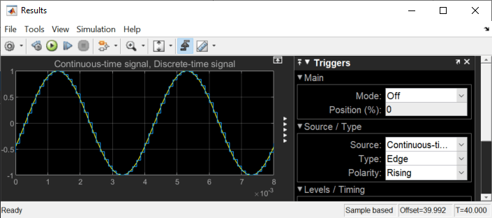
[ミックスドシグナル システム] テンプレートをクリックして、DSP System Toolbox およびミックスドシグナル システム用の推奨設定で構成された基本 A/D コンバーター モデルを作成します。このモデルは、アナログ アンチ エイリアシング フィルターの後にゼロ次ホールド回路を実装することで A/D 変換を実行します。モデルは、Simulink 内で、DSP System Toolbox を使用したミックスドシグナル システムのモデル化の開始点として機能します。離散時間信号はすべて、最速のサンプル レートを示す赤で表示されます。連続時間信号は黒で表示されます。その他のサンプル時間オプションについては、[デバッグ] タブの [情報のオーバーレイ]、[色] を選択します。
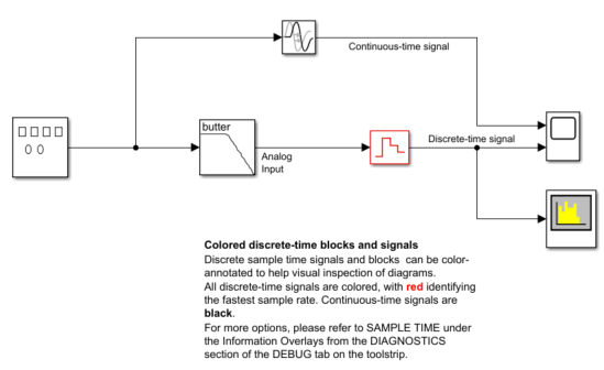
モデル内の Scope (Simulink) ブロックは、連続時間信号と離散時間信号をプロットします。
Spectrum Analyzer ブロックは、離散時間信号のスペクトルを示します。