Velocity Profiler
Generate velocity profile of vehicle path given kinematic constraints
Libraries:
Automated Driving Toolbox
Description
The Velocity Profiler block generates a velocity profile of a driving path that satisfies this set of specified kinematic constraints:
The maximum allowable speed of the vehicle
The maximum longitudinal acceleration and deceleration of the vehicle
The maximum longitudinal jerk of the vehicle
The maximum lateral acceleration of the vehicle
Specify the cumulative lengths along the path and the driving directions and curvatures at each point along the path. You can obtain these values from the output of a Path Smoother Spline block. Also specify the longitudinal velocity of the vehicle at the start and end of the path.
Use the generated velocity profile as the input reference velocities of a longitudinal controller, as shown in the Automated Parking Valet in Simulink example.
Examples
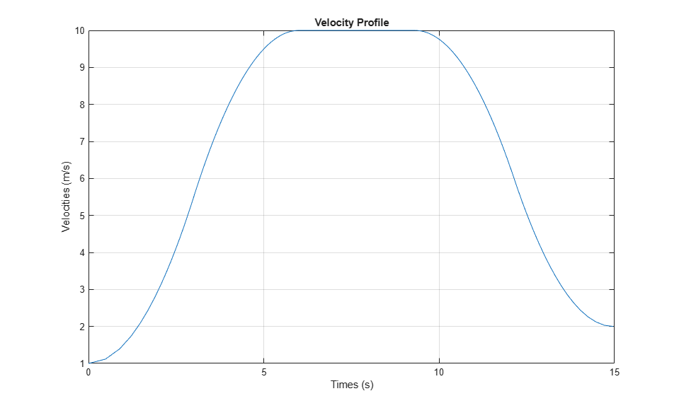
Velocity Profile of Straight Path
Generate a velocity profile for a straight driving path with no changes in direction.
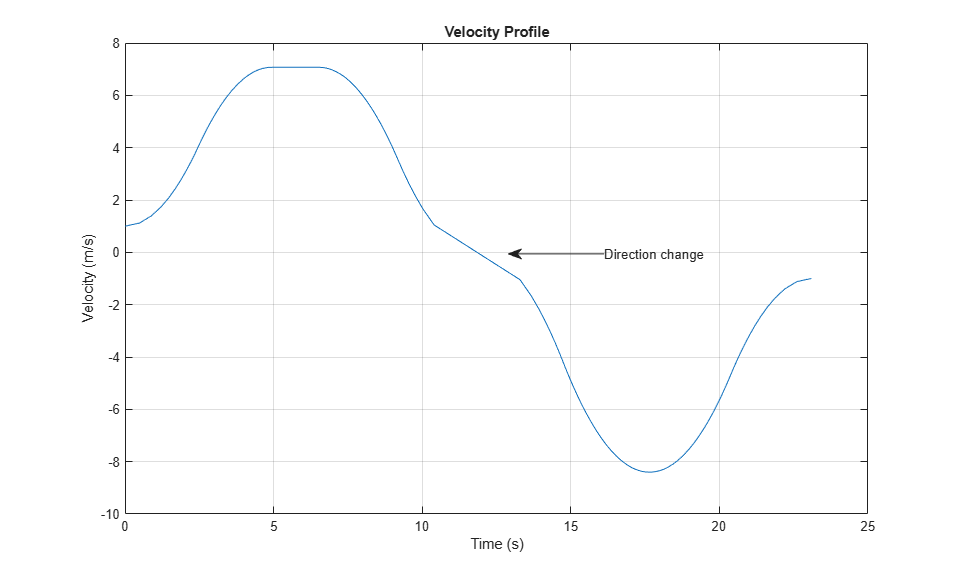
Velocity Profile of Path with Curve and Direction Change
Generate a velocity profile for a driving path that includes a curve and a change in direction.

Automated Parking Valet in Simulink
Construct an automated parking valet system in Simulink® with Automated Driving Toolbox™.
Ports
Input
Output
Parameters
More About
Algorithms
To generate the velocity profile for a reference path, the Velocity Profiler block performs these steps:
Generate a continuous velocity profile that satisfies all kinematic constraints (speed, acceleration, and jerk) specified by the block parameters.
Discretize the velocity profile by mapping poses in the reference path to velocity values, based on how far away the poses are from the starting pose. The cumulative path lengths specified in the CumLengths input port contain these distances. The Path Smoother Spline block returns these cumulative path lengths, along with the smooth path.
The generated velocity profile is a seven-interval curve. At each time interval within the
curve, the jerk, acceleration, and velocity of the vehicle change to satisfy the specified
constraints. The figure and table show how these values change for a vehicle traveling in
forward motion along a path. For simplicity, the starting and ending velocity of the vehicle,
as specified by the StartVelocity and EndVelocity
input ports, are both 0.

| Time Interval | Jerk | Acceleration | Velocity | Notes |
|---|---|---|---|---|
| 1 | Set to MaxJerk | Increases from 0 to MaxAccel | Increases from starting velocity | - |
| 2 | Set to 0 | Held constant at MaxAccel | Keeps increasing | During the previous interval, if the vehicle cannot reach
MaxAccel given the MaxSpeed constraint, then
interval 2 does not occur. |
| 3 | Set to -MaxJerk | Decreases from MaxAccel to 0 | Increases to MaxSpeed | - |
| 4 | Set to 0 | Held constant at 0 | Held constant at MaxSpeed | - |
| 5 | Set to -MaxJerk | Decreases from 0 to -MaxDecel | Starts decreasing | - |
| 6 | Set to 0 | Held constant at -MaxDecel | Keeps decreasing | During the previous interval, if the vehicle cannot reach
-MaxDecel given the MaxSpeed constraint, then
interval 6 does not occur. |
| 7 | Set to MaxJerk | Increases from -MaxDecel to 0 | Decreases to ending velocity | - |
In the figure and table:
MaxJerkand-MaxJerkare set by the Maximum longitudinal jerk (m/s^3) parameter.MaxAcceland-MaxDecelare set by the Maximum longitudinal acceleration (m/s^2) and Maximum longitudinal deceleration (m/s^2) parameters, respectively. You can specify asymmetric values for these parameters.MaxSpeedis set by the Maximum allowable speed (m/s) parameter.
For a vehicle in reverse motion, the curves in the figure are reversed. The signs of the parameter values shown in the figure and table are also reversed.
If the vehicle includes multiple changes in direction, the block generates separate velocity profiles for each driving direction. Then the block concatenates these profiles in the final Velocities output. For an example, see Velocity Profile of Path with Curve and Direction Change.
References
[1] Villagra, Jorge, Vicente Milanés, Joshué Pérez, and Jorge Godoy. "Smooth path and speed planning for an automated public transport vehicle." Robotics and Autonomous Systems. Vol. 60, Number 2, February 2012, pp. 252–265.
Extended Capabilities
Version History
Introduced in R2019b