Path Smoother Spline
Smooth vehicle path using cubic spline interpolation
Libraries:
Automated Driving Toolbox
Description
The Path Smoother Spline block generates a smooth vehicle path, consisting of a sequence of discretized poses, by fitting the input reference path poses to a cubic spline. Given the input reference path directions, the block also returns the directions that correspond to each pose.
Use this block to convert a C1-continuous path to a C2-continuous path. C1-continuous paths include Dubins or Reeds-Shepp paths that are returned by path planners. For more details on these path types, see C1-Continuous and C2-Continuous Paths.
You can use the returned poses and directions with a vehicle controller, such as the Lateral Controller Stanley block.
Examples

Automated Parking Valet in Simulink
Construct an automated parking valet system in Simulink® with Automated Driving Toolbox™.
Ports
Input
Output
Parameters
More About
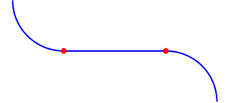
A path is C1-continuous if its derivative exists and is continuous. Paths that are only C1-continuous have discontinuities in their curvature. For example, a path composed of Dubins or Reeds-Shepp path segments has discontinuities in curvature at the points where the segments join. These discontinuities result in changes in direction that are not smooth enough for driving with passengers.
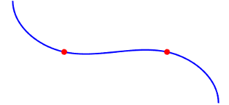
A path is also C2-continuous if its second derivative exists and is continuous. C2-continuous paths have continuous curvature and are smooth enough for driving with passengers.
Algorithms
The path-smoothing algorithm interpolates a parametric cubic spline that passes through all input reference pose points. The parameter of the spline is the cumulative chord length at these points. [1]
The tangent direction of the smoothed output path approximately matches the orientation angle of the vehicle at the starting and goal poses.
References
[1] Floater, Michael S. "On the Deviation of a Parametric Cubic Spline Interpolant from Its Data Polygon." Computer Aided Geometric Design. Vol. 25, Number 3, 2008, pp. 148–156.
[2] Lepetic, Marko, Gregor Klancar, Igor Skrjanc, Drago Matko, and Bostjan Potocnik. "Time Optimal Path Planning Considering Acceleration Limits." Robotics and Autonomous Systems. Vol. 45, Numbers 3–4, 2003, pp. 199–210.
Extended Capabilities
Version History
Introduced in R2019a