Simulation 3D Ultrasonic Sensor
Libraries:
Automated Driving Toolbox /
Simulation 3D
Aerospace Blockset /
Animation /
Simulation 3D
UAV Toolbox /
Simulation 3D
Simulink 3D Animation /
Simulation 3D /
Sensors
Description
Note
Simulating models with the Simulation 3D Ultrasonic Sensor block requires Simulink® 3D Animation™.
The Simulation 3D Ultrasonic Sensor block generates detections from range measurements taken by an ultrasonic sensor mounted on an ego vehicle in a 3D simulation environment rendered using the Unreal Engine® from Epic Games®. The block calculates range measurements based on the distance between the sensor and the closest point on the detected object.
If you set Sample time to -1, the block uses the
sample time specified in the Simulation 3D Scene Configuration block. To use
this sensor, you must include a Simulation 3D Scene Configuration block in your
model.
Tip
The Simulation 3D Scene Configuration
block must execute before the Simulation 3D Ultrasonic Sensor block. That
way, the Unreal Engine 3D visualization environment prepares the data before the Simulation 3D
Ultrasonic Sensor block receives it. To check the block execution order,
right-click the blocks and then click the Properties button ![]() . On the General tab, confirm these
Priority settings:
. On the General tab, confirm these
Priority settings:
Simulation 3D Scene Configuration —
0Simulation 3D Ultrasonic Sensor —
1
For more information about execution order, see How Unreal Engine Simulation for Automated Driving Works.
The Coordinate system parameter of the block specifies how the actor transformations are applied in the 3D environment. The output of the block also follows the specified coordinate system.
Examples
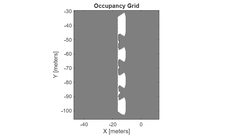
Build Occupancy Map Using Simulation 3D Ultrasonic Sensor
Build an occupancy map of a US city block using a Simulation 3D Ultrasonic Sensor block and Unreal Engine simulation environment.
Ports
Output
Object detections, returned as a Simulink bus containing a MATLAB® structure. For more details about buses, see Create Nonvirtual Buses (Simulink).
You can pass object detections from these sensors and other sensors to a tracker, such as a Multi-Object Tracker block, and generate tracks.
The structure contains these fields.
| Field | Description |
|---|---|
Time | Measurement time |
Measurement | Distance measurement to the closest object |
MeasurementNoise | Measurement noise covariance matrix |
SensorIndex | Unique ID of the sensor |
ObjectClassID | Object classification |
ObjectAttributes | Additional information passed to tracker |
MeasurementParameters | Parameters used by initialization functions of nonlinear Kalman tracking filters |
This table describes the additional information in the
ObjectAttributes field.
ObjectAttributes
| Attribute | Definition |
|---|---|
TargetIndex | Identifier of the actor that generated the detection, returned as the
value of the ActorID property of the actor. For false
alarms, this value is negative. |
PointOnTarget | Coordinate of the point on the detected object that the sensor used to compute the distance measurement, in the vehicle coordinate system. Use this for visualizing detections in the Bird's-Eye Scope app. |
For MeasurementParameters, the measurements are relative to
the parent frame. The parent frame is the ego vehicle body.
MeasurementParameters
| Parameter | Definition |
|---|---|
Frame | Enumerated type indicating the frame used to report measurements. If
the detections come from an Ultrasonic Detection Generator block, Simulation
3D Ultrasonic Sensor reports them in spherical coordinates, and the value of
Frame is 'spherical'. |
OriginPosition | 3-D vector offset of the sensor origin from the parent frame origin. |
OriginVelocity | Velocity of the sensor coordinate system with respect to the parent frame. |
IsParentToChild | Logical scalar indicating if Orientation performs a
frame rotation from the parent coordinate frame to the child coordinate
frame. When IsParentToChild is false,
then Orientation performs a frame rotation from the child
coordinate frame to the parent coordinate frame. |
HasAzimuth | Indicates whether measurements contain azimuth components. |
HasRange | Indicates whether measurements contain range components. Always
true for Ultrasonic Detection
Generator. |
HasElevation | Indicates whether measurements contain elevation components. Always
false for Ultrasonic Detection
Generator. |
HasVelocity | Indicates whether measurements contain velocity or range rate
components. Always false for Ultrasonic Detection
Generator. |
FieldOfView | 2-D vector containing the azimuth and elevation field-of-view values of the sensor. |
Dependencies
To enable this port, select the Use bus output parameter.
Detectable object present in the sensor field-of-view, returned as a Boolean scalar. An object is considered detectable if its closest distance to the sensor is greater than the minimum detection-only range specified in the Detection ranges (m) parameter.
Dependencies
To enable this port, clear the Use bus output parameter.
Range measurement is possible for an object present in the sensor field-of-view, returned as a Boolean scalar. For any object in the field-of-view, range measurement is possible if its closest distance to the sensor is greater than the minimum-distance range specified in the Detection ranges (m) parameter.
Dependencies
To enable this output port, clear the Use bus output parameter.
Distance measurement to the closest object, returned as a nonnegative scalar, in meters.
Dependencies
To enable this port, clear the Use bus output parameter.
Sensor location along the X-axis, Y-axis, and Z-axis of the scene. The Translation values are in the world coordinates of the scene. In this coordinate system, the Z-axis points up from the ground. Units are in meters.
Dependencies
To enable this port, on the Ground Truth tab, select Output location (m) and orientation (rad).
Data Types: double
Roll, pitch, and yaw sensor orientation about the X-axis, Y-axis, and Z-axis of the scene. The Rotation values are in the world coordinates of the scene. These values are positive in the clockwise direction when looking in the positive directions of these axes. Units are in radians.
Dependencies
To enable this port, on the Ground Truth tab, select Output location (m) and orientation (rad).
Data Types: double
Parameters
Mounting
Specify the unique identifier of the sensor. In a multisensor system, the sensor identifier enables you to distinguish between sensors. When you add a new sensor block to your model, the Sensor identifier of that block is N + 1, where N is the highest Sensor identifier value among the existing sensor blocks in the model.
Example: 2
Specify the name of the parent to which the sensor is mounted. The block provides a
list of parent actors in the model. The names that you can select correspond to the
values of the Name parameters of the Simulation 3D
blocks in your model. If you select Scene Origin, the block
places a sensor at the scene origin. The Custom option allows
you to specify the name of any actor, including child actors in the environment, as the
parent actor.
Example: SimulinkVehicle1
Specify the name of custom parent. This parameter allows you to set any actor in the environment, including child actors as the parent actor to which the sensor is mounted. The name corresponds to the Name parameter of the Simulation 3D block.
Example: SimulinkVehicle1
Dependencies
To enable this parameter, set Parent name to
Custom.
Specify the coordinate system that the actor uses for translation and rotation in the 3D environment.
Default– World coordinate system. Units are in m and rad.MATLAB– MATLAB coordinate system. Units are in m and rad.ISO8855– ISO 8855 standard coordinate system. Units are in m and deg.AERO– SAE coordinate system. Units are in m and rad.VRML– X3D ISO standard coordinate system. Units are in m and rad.SAE– SAE coordinate system. Units are in m and rad.
For more details on the different coordinate systems, see Coordinate Systems for Unreal Engine Simulation in Automated Driving Toolbox.
Example: MATLAB
Sensor mounting location. By default, the block places the sensor relative to the scene or vehicle origin, depending on the Parent name parameter.
When Parent name is
Scene
                            Origin
, the block mounts the sensor to the origin of the scene. You can set the Mounting location toOriginonly. During simulation, the sensor remains stationary.When Parent name is
sim3dactor name, the block mounts the sensor to the origin of the actor, which is the center of the shape. You can set the Mounting location toOriginonly. During simulation, the sensor travels with the actor.When Parent name is the name of a vehicle, the block mounts the sensor to one of the predefined mounting locations described in the table. During simulation, the sensor travels with the vehicle.
| Mounting Location | Description | Orientation Relative to Vehicle Origin [Roll, Pitch, Yaw] (deg) |
|---|---|---|
Origin | Forward-facing sensor mounted to the vehicle origin, which is on the ground and at the geometric center of the vehicle (see Coordinate Systems for Unreal Engine Simulation in Automated Driving Toolbox) | [0, 0, 0] |
| Forward-facing sensor mounted to the front bumper | [0, 0, 0] |
| Backward-facing sensor mounted to the rear bumper | [0, 0, 180] |
Right mirror | Downward-facing sensor mounted to the right side-view mirror | [0, –90, 0] |
Left mirror | Downward-facing sensor mounted to the left side-view mirror | [0, –90, 0] |
Rearview mirror | Forward-facing sensor mounted to the rearview mirror, inside the vehicle | [0, 0, 0] |
Hood center | Forward-facing sensor mounted to the center of the hood | [0, 0, 0] |
Roof center | Forward-facing sensor mounted to the center of the roof | [0, 0, 0] |
Roll, pitch, and yaw are clockwise-positive when looking in the positive direction of the X-axis, Y-axis, and Z-axis, respectively. When looking at a vehicle from above, the yaw angle (the orientation angle) is counterclockwise-positive because you are looking in the negative direction of the axis.
The X-Y-Z mounting location of the sensor relative to the vehicle depends on the vehicle type. To specify the vehicle type, use the Type parameter of the Simulation 3D Vehicle with Ground Following to which you mount the sensor. To obtain the X-Y-Z mounting locations for a vehicle type, see the reference page for that vehicle.
To determine the location of the sensor in world coordinates, open the sensor block. Then, on the Ground Truth tab, select the Output location and orientation parameter and inspect the data from the Translation output port.
Select this parameter to specify an offset from the mounting location by using the Relative translation [X, Y, Z] (m) and Relative rotation [Roll, Pitch, Yaw] (deg) parameters.
Translation offset relative to the mounting location of the sensor, specified as a real-valued 1-by-3 vector of the form [X, Y, Z]. Units are in meters.
If you mount the sensor to a vehicle by setting Parent name to the name of that vehicle, then X, Y, and Z are in the vehicle coordinate system, where:
The X-axis points forward from the vehicle.
The Y-axis points to the left of the vehicle, as viewed when looking in the forward direction of the vehicle.
The Z-axis points up.
The origin is the mounting location specified in the Mounting location parameter. This origin is different from the vehicle origin, which is the geometric center of the vehicle.
If you mount the sensor to the scene origin
by setting Parent name to Scene Origin,
then X, Y, and Z are in
the world coordinates of the scene.
For more details about the vehicle and world coordinate systems, see Coordinate Systems for Unreal Engine Simulation in Automated Driving Toolbox.
Example: [0,0,0.01]
Dependencies
To enable this parameter, select Specify offset.
Rotational offset relative to the mounting location of the sensor, specified as a real-valued 1-by-3 vector of the form [Roll, Pitch, Yaw]. Roll, pitch, and yaw are the angles of rotation about the X-, Y-, and Z-axes, respectively. The rotation order is Roll, then Pitch, then Yaw. When you update any of the three rotation values and leave others unchanged, the software reapplies all three rotations in the same order.
If you mount the sensor to a vehicle by setting Parent name to the name of that vehicle, then X, Y, and Z are in the vehicle coordinate system, where:
The X-axis points forward from the vehicle.
The Y-axis points to the left of the vehicle, as viewed when looking in the forward direction of the vehicle.
The Z-axis points up.
Roll, pitch, and yaw are clockwise-positive when looking in the forward direction of the X-axis, Y-axis, and Z-axis, respectively. If you view a scene from a 2D top-down perspective, then the yaw angle (also called the orientation angle) is counterclockwise-positive because you are viewing the scene in the negative direction of the Z-axis.
The origin is the mounting location specified in the Mounting location parameter. This origin is different from the vehicle origin, which is the geometric center of the vehicle.
If you mount the sensor to the
scene origin by setting Parent name to Scene
Origin, then X, Y, and
Z are in the world coordinates of the scene.
For more details about the vehicle and world coordinate systems, see Coordinate Systems for Unreal Engine Simulation in Automated Driving Toolbox.
Example: [0,0,10]
Dependencies
To enable this parameter, select Specify offset.
Sample time of the block, in seconds, specified as a positive scalar. The 3D simulation environment frame rate is the inverse of the sample time.
If you set the sample time to -1, the block inherits its sample time from
the Simulation 3D Scene Configuration block.
Sensor Parameters
Detection range vector of the ultrasonic sensor, specified as a 1-by-3 nonnegative
real-valued vector of the form [minDetOnlyRange minDistRange
maxDistRange], where minDetOnlyRange < minDistRange <
maxDistRange. Units are in meters. These values determine the detections
and distance values returned by the ultrasonic sensor.
When the detected object is at a distance between
minDistRangeandmaxDistRange, the sensor returns a positive distance value.When the detected object is at a distance between
minDetOnlyRangeandminDistRange, the sensor detects the object, but cannot determine the distance and returns a value of0.When the object is at a distance below
minDetOnlyRangeor abovemaxDistRange, the sensor returns an empty cell array.
Horizontal field of view of ultrasonic sensor, specified as a positive real
scalar. This field of view defines the total angular extent spanned by the sensor in
the horizontal direction. You must specify the horizontal field of view
horizontalFOV in the range (0, 90). Units are in degrees.
Vertical field of view of ultrasonic sensor, specified as a positive real scalar. This field of view defines the total angular extent spanned by the sensor in the vertical direction. You must specify the vertical field of view in the range (0, 90). Units are in degrees.
Select to output detections as a bus signal using the Detections port. Clear Use bus output to instead enable the Has object, Has range, and Range output ports.
Ground Truth
Select this parameter to output the translation and rotation of the sensor at the Translation and Rotation ports, respectively.
Version History
Introduced in R2022bSetting the Parent name to
Custom enables the Custom parent name parameter,
with which you can specify the name of the actor to which you want to mount the sensor.
Simulating models with the Simulation 3D Ultrasonic Sensor block requires Simulink 3D Animation.
Simulation 3D Ultrasonic Sensor block now has ground truth parameter that you can enable to output the location and orientation of the sensor.
MATLAB Command
You clicked a link that corresponds to this MATLAB command:
Run the command by entering it in the MATLAB Command Window. Web browsers do not support MATLAB commands.
Web サイトの選択
Web サイトを選択すると、翻訳されたコンテンツにアクセスし、地域のイベントやサービスを確認できます。現在の位置情報に基づき、次のサイトの選択を推奨します:
また、以下のリストから Web サイトを選択することもできます。
最適なサイトパフォーマンスの取得方法
中国のサイト (中国語または英語) を選択することで、最適なサイトパフォーマンスが得られます。その他の国の MathWorks のサイトは、お客様の地域からのアクセスが最適化されていません。
南北アメリカ
- América Latina (Español)
- Canada (English)
- United States (English)
ヨーロッパ
- Belgium (English)
- Denmark (English)
- Deutschland (Deutsch)
- España (Español)
- Finland (English)
- France (Français)
- Ireland (English)
- Italia (Italiano)
- Luxembourg (English)
- Netherlands (English)
- Norway (English)
- Österreich (Deutsch)
- Portugal (English)
- Sweden (English)
- Switzerland
- United Kingdom (English)