AGC
Adaptively adjust gain for constant signal-level output
Libraries:
Communications Toolbox /
RF Impairments Correction
Description
The automatic gain controller (AGC) block adaptively adjusts its gain to achieve a constant signal level at the output.
This icon shows the AGC block with the optional Px port.![]()
Examples
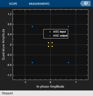
The doc_agc_received_signal_amplitude model uses an AGC block to adjust the received signal power to approximately 1 watt.
A constellation diagram displays the signal before and after the signal level is adjusted by the AGC block. Random integer-valued symbols are QPSK modulated and then the signal level is scaled down by using a Gain block. The AGC block adjusts the signal to achieve a desired power level of 1 W. A constellation diagram displays the signal input to and output from the AGC block.
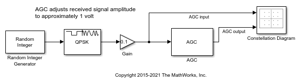
Run the model and display the constellation diagram to show the signal level adjustments performed by the AGC block.
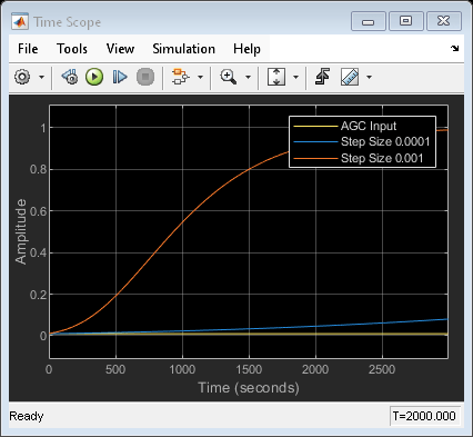
This model uses AGC blocks with different step size settings to adjust the received signal power.
A time scope plots the effect of step size on AGC performance. Random integer-valued symbols are QPSK modulated and then the signal level is scaled down by using a Gain block. Three signal branches flow to a time scope to plot the received signal magnitude with no AGC, AGC with step size set to 0.0001, and AGC with step size set to 0.001.
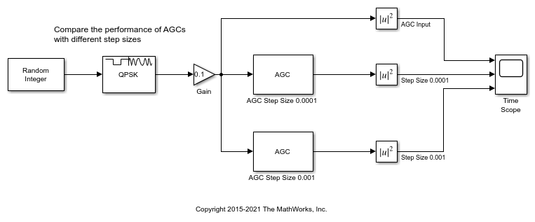
Run the model and display the time scope to show the signal level adjustments performed by the AGC blocks.
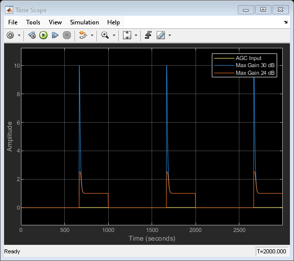
This model uses AGC blocks with different maximum gain settings to adjust the received signal power.
A time scope plots the effect of maximum gain on AGC performance. The maximum gain setting affects the ability of the AGC to reach its target output power. Random integer-valued symbols are QPSK modulated and then the signal level is scaled down by using a Gain block. Three signal branches flow to a time scope to plot the received signal magnitude with no AGC, AGC with maximum gain set to 30 dB, and AGC with maximum gain set to 24 dB.

Run the model and display the time scope to show the signal level adjustments performed by the AGC blocks.
Ports
Input
Output
Parameters
Block Characteristics
Data Types |
|
Multidimensional Signals |
|
Variable-Size Signals |
|
More About
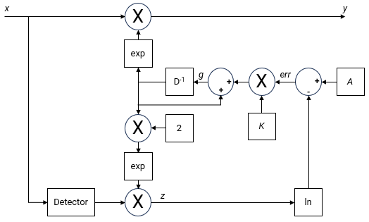
The AGC implementation uses a logarithmic feedback loop. As this figure of the logarithmic-loop AGC algorithm shows, the output signal is the product of the input signal and the exponential of the loop gain. The error signal is the difference between the reference level and the product of the logarithm of the detector output and the exponential of the loop gain. After multiplying by the step size, the AGC passes the error signal to an integrator.
The logarithmic-loop AGC performs well for a variety of signal types, including amplitude modulation. The AGC Detector is applied to the input signal, which improves convergence times, but increases signal power variation at the detector input. Large signal variation at the detector input is acceptable for floating-point systems.
Mathematically, the algorithm is summarized as
where:
x is the input signal.
y is the output signal.
g is the loop gain.
Detector(•) is the detector function.
z is the detector output.
A is the reference value.
err is the error signal.
K is the step size.
Tips
This block is designed for streaming applications.
If the signal amplitude does not change within the frame, you can simulate an ideal AGC by calculating the average gain desired for a frame of samples. Then, apply the gain to each sample in the frame.
If you use the AGC with higher order QAM signals, you might need to reduce the variation in the gain during steady-state operation. Inspect the constellation diagram at the output of the AGC during steady-state operation. You can increase the averaging length to avoid frequent gain adjustments. An increase in averaging length reduces execution speed.
Extended Capabilities
Version History
Introduced in R2013a