NR PUCCH のブロック エラー レート
この例では、5G Toolbox™ の機能を使用し、5G NR リンクの物理アップリンク制御チャネル (PUCCH) で送信されたアップリンク制御情報 (UCI) のブロック エラー レート (BLER) を測定する方法を示します。
はじめに
この例では、5G リンクの PUCCH フォーマット 3 で送信された UCI の BLER を測定します。
UCI の BLER は、UCI が送信されたときに UCI が間違って復号化される確率として定義されます。
は、送信された UCI が間違って復号化されたインスタンスの数。
は、UCI が送信されたインスタンスの数。
この例では、次の 5G NR の機能をモデル化します。
UCI の符号化と復号化
PUCCH および関連付けられた復調基準信号 (DM-RS)
OFDM の変調と復調
タップ付き遅延線 (TDL) の伝播チャネル
この例では、さらに次の機能をシミュレートします。
完全な同期と完全なチャネル推定、あるいは実用的な同期と実用的なチャネル推定
イコライズ
シミュレーションの合計時間を短縮するためには、Parallel Computing Toolbox™ の機能を使用して SNR ループの S/N 比 (SNR) 点を並列に処理します。
シミュレーションの長さと SNR 点
シミュレーションの長さを 10 ms のフレームの数で設定します。有意なスループットの結果を得るためには、多数の NFrames を使用しなければなりません。シミュレーションを行うための SNR 点を設定します。SNR はリソース エレメント (RE) ごとに定義され、それぞれの受信アンテナに適用されます。この例で使用している SNR 定義の説明については、リンク シミュレーションで使用する SNR の定義を参照してください。
simParameters = struct;         % Create simParameters structure
simParameters.NFrames = 5;      % Number of 10 ms frames
simParameters.SNRIn = -14:2:-4; % SNR range (dB)
変数 displaySimulationInformation を true に設定し、各 SNR 点における BLER シミュレーションの情報を表示します。
displaySimulationInformation =  true;
true;キャリアと PUCCH の構成
次のプロパティを使ってキャリアを設定します。
物理レイヤーのセル ID
サブキャリア間隔 (SCS) (kHz)
サイクリック プレフィックス
リソース ブロック (RB) の帯域幅。各 RB に含まれるサブキャリアは 12 個
共通リソース ブロック 0 (CRB 0) を基準とした、キャリアの先頭 RB
次のプロパティを使って PUCCH フォーマット 3 構成を設定します。
割り当てられた RB のセット
シンボルの割り当て ([S L])
変調スキーム
周波数ホッピングの構成
2 番目のホップの先頭 RB
グループ ホッピングの構成
スクランブリング アイデンティティ
追加の DM-RS 構成
シミュレーション全体で使用する次の追加パラメーターを設定します。
送信アンテナの数
受信アンテナの数
% Set carrier resource grid properties (15 kHz SCS and 10 MHz bandwidth) carrier = nrCarrierConfig; carrier.NCellID =0; carrier.SubcarrierSpacing =
15; carrier.CyclicPrefix =
"normal"; carrier.NSizeGrid = 52; carrier.NStartGrid = 0; % Set PUCCH format 3 properties pucch = nrPUCCH3Config; pucch.PRBSet = 0; pucch.SymbolAllocation = [0 14]; pucch.Modulation =
"QPSK"; pucch.FrequencyHopping =
"intraSlot"; pucch.SecondHopStartPRB = (carrier.NSizeGrid-1) - (numel(pucch.PRBSet)-1); pucch.GroupHopping =
"neither"; pucch.HoppingID = 0; pucch.NID = []; pucch.RNTI =
1; pucch.AdditionalDMRS =
0; % Set number of transmit and receive antennas simParameters.NTxAnts =
1; simParameters.NRxAnts =
2;
UCI 構成
NumUCIBits フィールドは、UCI ペイロードの生成に使用されるランダムな UCI ビットの数を示します。UCI ビットの数は、3 ~ 1706 の範囲でなければなりません。
simParameters.NumUCIBits =16; % Number of UCI bits
チャネル推定器の構成
logical 変数 perfectChannelEstimator は、チャネル推定と同期の動作を制御します。この値を true に設定すると、完全なチャネル推定と同期が使用されます。それ以外の場合、受信した PUCCH DM-RS の値に基づき、実用的なチャネル推定と同期が使用されます。
perfectChannelEstimator =  true;
true;伝播チャネル モデルの構成
TS 38.104 の Annex G、Table G.2.1.1-4 で規定された 'TDLC300-100 Low' の構成を使用し、TDL チャネル モデルを作成します。
% Set up TDL channel
channel = nrTDLChannel;
channel.DelayProfile = 'TDLC300';
channel.MaximumDopplerShift = 100; % in Hz
channel.MIMOCorrelation = 'low';
channel.TransmissionDirection = 'Uplink';
channel.NumTransmitAntennas = simParameters.NTxAnts;
channel.NumReceiveAntennas = simParameters.NRxAnts;
関数nrOFDMInfoから返された値を使用して、チャネル モデルのサンプル レートを設定します。
waveformInfo = nrOFDMInfo(carrier);
channel.SampleRate = waveformInfo.SampleRate;
処理ループと結果
各 SNR 点における UCI の BLER を判定するため、PUCCH で送信された UCI を以下の手順を使用して送信インスタンスごとに解析します。
リソース グリッドの生成: 関数
nrUCIEncodeを使用し、UCI を符号化します。関数nrPUCCHを使用し、符号化された UCI を変調します。変調されたシンボルに、実装固有の多入力多出力 (MIMO) プリコーディングを適用します。この変調されたシンボルと基準信号をリソース グリッドにマッピングします。波形の生成: 関数
nrOFDMModulateを使用し、生成されたグリッドを OFDM 変調して時間領域波形を取得します。ノイズを含むチャネルのモデル化と適用: 生成された波形を TDL フェージング チャネルに渡し、劣化した波形を取得します。次に、劣化した波形に加法性ホワイト ガウス ノイズ (AWGN) を追加します。各レイヤーの SNR は、受信アンテナ単位で RE ごとに定義されます。この例で使用している SNR 定義の説明については、リンク シミュレーションで使用する SNR の定義を参照してください。
同期と OFDM 復調の実行: 完全な同期では、チャネルのパス ゲインとパス フィルターを使用します。実用的な同期の場合は、受信波形と PUCCH DM-RS の相関をとります。次に、関数
nrOFDMDemodulateを使用し、同期した信号を OFDM 復調します。チャネル推定の実行: 完全なチャネル推定では、チャネル スナップショットのパス ゲイン、パス フィルター、およびサンプル時間を使用します。実用的なチャネル推定の場合は、PUCCH DM-RS を使用します。
PUCCH の抽出とイコライズの実行: 関数
nrExtractResourcesを使用し、受信した OFDM リソース グリッドと推定されたチャネル グリッドに基づいて PUCCH 割り当てに対応する RE を抽出します。次に、関数nrEqualizeMMSEを使用し、受信した PUCCH の RE をイコライズします。PUCCH の復号化: イコライズされた PUCCH シンボルを推定ノイズとともに復調してデスクランブルし、受信コードワードの推定値を取得します。
UCI の復号化: 復号化されたコードワードを関数
nrUCIDecodeに渡し、UCI を間違って復号化したインスタンスの数を記録します。
% Obtain channel information
chInfo = info(channel);

% Specify array to store output(s) for all SNR points
blerUCI = zeros(length(simParameters.SNRIn),1);

% Assign temporary variables for parallel simulation
nTxAnts = simParameters.NTxAnts;
nRxAnts = simParameters.NRxAnts;
snrIn = simParameters.SNRIn;
nFrames = simParameters.NFrames;
ouci = simParameters.NumUCIBits;
nFFT = waveformInfo.Nfft;
symbolsPerSlot = carrier.SymbolsPerSlot;
slotsPerFrame = carrier.SlotsPerFrame;

% Validate number of frames
validateattributes(nFrames,{'double'},{'scalar','positive','integer'},'','simParameters.NFrames')

% Validate SNR range
validateattributes(snrIn,{'double'},{'real','vector','finite'},'','simParameters.SNRIn')

% Validate PUCCH configuration
classPUCCH = validatestring(class(pucch),{'nrPUCCH2Config','nrPUCCH3Config','nrPUCCH4Config'},'','class of PUCCH');
formatPUCCH = classPUCCH(8);

% The temporary variables carrier_init and pucch_init are used to
% create the temporary variables carrier and pucch in the SNR loop
% to create independent instances in case of parallel simulation.
carrier_init = carrier;
pucch_init = pucch;

for snrIdx = 1:numel(snrIn) % Comment out for parallel computing
% parfor snrIdx = 1:numel(snrIn) % Uncomment for parallel computing
    % To reduce the total simulation time, you can execute this loop in
    % parallel by using Parallel Computing Toolbox features. Comment out the
    % for-loop statement and uncomment the parfor-loop statement. If
    % Parallel Computing Toolbox is not installed, parfor-loop defaults to
    % a for-loop statement. Because the parfor-loop iterations are executed
    % in parallel in a nondeterministic order, the simulation information
    % displayed for each SNR point can be intertwined. To switch off the
    % simulation information display, set the displaySimulationInformation
    % variable (defined earlier in this example) to false.

    % Reset the random number generator and channel so that each SNR point
    % experiences the same noise and channel realizations.
    rng(0,'twister')
    reset(channel)

    % Initialize variables for this SNR point (required when using
    % Parallel Computing Toolbox)
    carrier = carrier_init;
    pucch = pucch_init;
    pathFilters = [];

    % Get operating SNR value
    SNRdB = snrIn(snrIdx);

    % Get total number of slots in the simulation period
    NSlots = nFrames*slotsPerFrame;

    % Set timing offset, which is updated in every slot for perfect
    % synchronization and when correlation is strong for practical
    % synchronization
    offset = 0;

    % Set variable to store block errors for each SNR point with 0
    ucierr = 0;
    for nslot = 0:NSlots-1

        % Update carrier slot number to account for new slot transmission
        carrier.NSlot = nslot;

        % Get PUCCH resources
        [pucchIndices,pucchIndicesInfo] = nrPUCCHIndices(carrier,pucch);
        dmrsIndices = nrPUCCHDMRSIndices(carrier,pucch);
        dmrsSymbols = nrPUCCHDMRS(carrier,pucch);

        % Create random UCI bits
        uci = randi([0 1],ouci,1);

        % Perform UCI encoding
        codedUCI = nrUCIEncode(uci,pucchIndicesInfo.G);

        % Perform PUCCH modulation
        pucchSymbols = nrPUCCH(carrier,pucch,codedUCI);

        % Create resource grid associated with PUCCH transmission antennas
        pucchGrid = nrResourceGrid(carrier,nTxAnts);

        % Perform implementation-specific PUCCH MIMO precoding and mapping
        F = eye(1,nTxAnts);
        [~,pucchAntIndices] = nrExtractResources(pucchIndices,pucchGrid);
        pucchGrid(pucchAntIndices) = pucchSymbols*F;

        % Perform implementation-specific PUCCH DM-RS MIMO precoding and mapping
        [~,dmrsAntIndices] = nrExtractResources(dmrsIndices,pucchGrid);
        pucchGrid(dmrsAntIndices) = dmrsSymbols*F;

        % Perform OFDM modulation
        txWaveform = nrOFDMModulate(carrier,pucchGrid);

        % Pass data through the channel model. Append zeros at the end of
        % the transmitted waveform to flush the channel content. These
        % zeros take into account any delay introduced in the channel. This
        % delay is a combination of the multipath delay and implementation
        % delay. This value can change depending on the sampling rate,
        % delay profile, and delay spread.
        txWaveformChDelay = [txWaveform; zeros(chInfo.MaximumChannelDelay,size(txWaveform,2))];
        [rxWaveform,pathGains,sampleTimes] = channel(txWaveformChDelay);

        % Add AWGN to the received time domain waveform. Normalize the
        % noise power by the size of the inverse fast Fourier transform
        % (IFFT) used in OFDM modulation, because the OFDM modulator
        % applies this normalization to the transmitted waveform. Also,
        % normalize the noise power by the number of receive antennas,
        % because the default behavior of the channel model is to apply
        % this normalization to the received waveform.
        SNR = 10^(SNRdB/20);
        N0 = 1/(sqrt(2.0*nRxAnts*nFFT)*SNR);
        noise = N0*complex(randn(size(rxWaveform)),randn(size(rxWaveform)));
        rxWaveform = rxWaveform + noise;

        % Perform synchronization
        if perfectChannelEstimator == 1
            % For perfect synchronization, use the information provided by
            % the channel to find the strongest multipath component.
            pathFilters = getPathFilters(channel);
            [offset,mag] = nrPerfectTimingEstimate(pathGains,pathFilters);
        else
            % For practical synchronization, correlate the received
            % waveform with the PUCCH DM-RS to give timing offset estimate
            % t and correlation magnitude mag. The function hSkipWeakTimingOffset
            % is used to update the receiver timing offset. If the correlation
            % peak in mag is weak, the current timing estimate t is ignored
            % and the previous estimate offset is used.
            [t,mag] = nrTimingEstimate(carrier,rxWaveform,dmrsIndices,dmrsSymbols);
            offset = hSkipWeakTimingOffset(offset,t,mag);

            % Display a warning if the estimated timing offset exceeds the
            % maximum channel delay
            if offset > chInfo.MaximumChannelDelay
                warning(['Estimated timing offset (%d) is greater than the maximum channel delay (%d).' ...
                    ' This will result in a decoding failure. This may be caused by low SNR,' ...
                    ' or not enough DM-RS symbols to synchronize successfully.'],offset,chInfo.MaximumChannelDelay);
            end
        end
        rxWaveform = rxWaveform(1+offset:end,:);

        % Perform OFDM demodulation on the received data to recreate the
        % resource grid. Include zero padding in the event that practical
        % synchronization results in an incomplete slot being demodulated.
        rxGrid = nrOFDMDemodulate(carrier,rxWaveform);
        [K,L,R] = size(rxGrid);
        if (L < symbolsPerSlot)
            rxGrid = cat(2,rxGrid,zeros(K,symbolsPerSlot-L,R));
        end

        % Perform channel estimation
        if perfectChannelEstimator == 1
            % For perfect channel estimation, use the value of the path
            % gains provided by the channel.
            estChannelGrid = nrPerfectChannelEstimate(carrier,pathGains,pathFilters,offset,sampleTimes);

            % Get the perfect noise estimate (from the noise realization).
            noiseGrid = nrOFDMDemodulate(carrier,noise(1+offset:end,:));
            noiseEst = var(noiseGrid(:));

            % Apply MIMO deprecoding to estChannelGrid to give an
            % estimate per transmission layer.
            K = size(estChannelGrid,1);
            estChannelGrid = reshape(estChannelGrid,K*symbolsPerSlot*nRxAnts,nTxAnts);
            estChannelGrid = estChannelGrid*F.';
            estChannelGrid = reshape(estChannelGrid,K,symbolsPerSlot,nRxAnts,[]);
        else
            % For practical channel estimation, use PUCCH DM-RS.
            [estChannelGrid,noiseEst] = nrChannelEstimate(carrier,rxGrid,dmrsIndices,dmrsSymbols);
        end

        % Get PUCCH REs from received grid and estimated channel grid
        [pucchRx,pucchHest] = nrExtractResources(pucchIndices,rxGrid,estChannelGrid);

        % Perform equalization
        [pucchEq,csi] = nrEqualizeMMSE(pucchRx,pucchHest,noiseEst);

        % Decode PUCCH symbols
        [uciLLRs,rxSymbols] = nrPUCCHDecode(carrier,pucch,ouci,pucchEq,noiseEst);

        % Decode UCI
        decucibits = nrUCIDecode(uciLLRs{1},ouci);

        % Store values to calculate BLER
        ucierr = ucierr + (~isequal(decucibits,uci));

    end

    % Calculate UCI BLER for each SNR point
    blerUCI(snrIdx) = ucierr/NSlots;

    % Display results dynamically
    if displaySimulationInformation == 1
        fprintf(['UCI BLER of PUCCH format ' formatPUCCH ' for ' num2str(nFrames) ' frame(s) at SNR ' num2str(snrIn(snrIdx)) ' dB: ' num2str(blerUCI(snrIdx)) '\n'])
    end
end
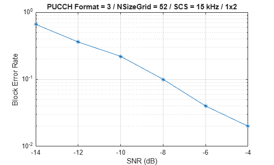
UCI BLER of PUCCH format 3 for 5 frame(s) at SNR -14 dB: 0.66
UCI BLER of PUCCH format 3 for 5 frame(s) at SNR -12 dB: 0.36
UCI BLER of PUCCH format 3 for 5 frame(s) at SNR -10 dB: 0.22
UCI BLER of PUCCH format 3 for 5 frame(s) at SNR -8 dB: 0.1
UCI BLER of PUCCH format 3 for 5 frame(s) at SNR -6 dB: 0.04
UCI BLER of PUCCH format 3 for 5 frame(s) at SNR -4 dB: 0.02
% Plot results
figure
semilogy(snrIn,blerUCI,'-*')
grid on
xlabel('SNR (dB)')
ylabel('Block Error Rate')
title(sprintf('PUCCH Format = %s / NSizeGrid = %d / SCS = %d kHz / %dx%d',...
    formatPUCCH,carrier_init.NSizeGrid,carrier_init.SubcarrierSpacing,nTxAnts,nRxAnts))
次の図では、SCS 30 kHz、占有送信帯域幅 20 MHz のキャリアについて、1500 フレーム (NFrames = 1500、SNRIn = -15:3:3) をシミュレートして得られた BLER の結果を示しています。このシミュレーションの設定には、UCI ビットの数が 16 に設定され、変数 perfectChannelEstimator が false に設定された、この例で配置した既定の PUCCH フォーマット 3 構成が含まれています。

その他の調査
各 SNR 点における UCI BLER を解析するには、変数
perfectChannelEstimatorの値を切り替え、SNR 値の範囲を変更します。さまざまなシナリオの BLER のパフォーマンスを確認するには、キャリアの numerology、送信アンテナと受信アンテナの数、およびチャネル モデルを変更します。
PUCCH フォーマット 2 および 4 の BLER のパフォーマンスを観察するには、キャリアと PUCCH の構成のセクションで、変数
pucchにそれぞれnrPUCCH2ConfigオブジェクトおよびnrPUCCH4Configオブジェクトを使用します。
まとめ
この例では、PUCCH フォーマット 3 で UCI が送信されたときの UCI の BLER を測定する方法を示しています。また、この例では、BLER を SNR の関数として表示およびプロットしています。
参考文献
3GPP TS 38.211. "NR; Physical channels and modulation (Release 15)." 3rd Generation Partnership Project; Technical Specification Group Radio Access Network.
3GPP TS 38.212. "NR; Multiplexing and channel coding (Release 15)." 3rd Generation Partnership Project; Technical Specification Group Radio Access Network.
3GPP TS 38.104. “NR; Base Station (BS) radio transmission and reception (Release 15).” 3rd Generation Partnership Project; Technical Specification Group Radio Access Network.