Modeling and Testing an 802.11ax RF Receiver with 5G Interference
The example shows how to characterize the impact of RF impairments on the reception of an IEEE® 802.11ax™ waveform coexisting with an adjacent 5G or 802.11ax interferer. The example generates the baseband waveforms by using WLAN Toolbox™ and 5G Toolbox™ and models the RF receiver by using RF Blockset™. The example does not require 5G Toolbox if it models an 802.11ax interferer.
Introduction
This example characterizes the impact of an adjacent 5G or 802.11ax interferer on the RF reception of an 802.11ax waveform. To evaluate the impact of the interference, the example performs these measurements:
Error vector magnitude (EVM): vector difference between the ideal (transmitted) signal and the measured (received) signal
Adjacent channel rejection (ACR): power difference between the desired signal and an interfering signal in the adjacent channel
Packet error rate (PER): number of packets containing errors divided by the total number of received packets
The impact of the receiver RF impairments such as phase noise and amplifier nonlinearities are also considered.
The example works on a packet-by-packet basis and uses a Simulink model to perform these steps:
Generate the baseband 802.11ax waveform (desired) by using WLAN Toolbox features.
Generate the baseband 5G waveform (interferer) by using 5G Toolbox features. You can generate an 802.11ax interferer by using WLAN Toolbox features instead. Alternatively, you can remove the interference.
Match the sampling rate of the two signals by using the Sample-Rate Match block.
To capture spectral regrowth of the combined bandwidth, oversample the waveforms by a factor of 10 by using an FIR Interpolation block.
Measure and display the ACR by calculating the power difference between both waveforms.
Aggregate both waveforms by using the Multiband Combiner block.
Import the combined waveform into the RF Receiver Subsystem block implemented by using RF Blockset blocks. The model provides an RF frequency to the combined waveform to carry the baseband information in RF Blockset.
Model the effects of downconverting the combined waveform to an intermediate frequency by using the RF Receiver Subsystem block. This block models the impairments introduced by an RF receiver using RF Blockset blocks.
Downsample the desired HE waveform by using an FIR Decimation block to compensate for the upsampling performed by the FIR Interpolation block.
Downsample the desired HE waveform by using an FIR Rate Conversion block to compensate for any upsampling performed by the Sample-Rate Match block.
Extract the data symbols and measure the EVM by demodulating the baseband waveform.
Calculate the PER by extracting the received bits and comparing them to the transmitted bits.
The Simulink model uses WLAN Toolbox, 5G Toolbox, and DSP System Toolbox™ features to process the baseband waveforms (steps 1-6 and 9-12) and uses RF Blockset blocks to model the RF receiver (steps 7 and 8). This model supports Normal and Accelerator simulation modes.
Simulink Model Structure
The model contains three main parts:
Baseband Waveform Generation: generates and combines the baseband 802.11ax and 5G waveforms
RF Reception: models the effects of downconverting the combined waveform to an intermediate frequency
Baseband Waveform Reception: calculates EVM and PER
modelName = 'HERFReceiverNRInterfererModel';
open_system(modelName);

Baseband Waveform Generation
The WLAN 802.11ax block generates standard-compliant high-efficiency single-user (HE SU) waveforms, according to IEEE Std 802.11ax-2021. You can generate this block using the WLAN Waveform Generator app. You can access the waveform configuration parameters in the user data of the block. This example uses the InitFcn in the Model callbacks to store the structure available in the user data in a Base Workspace variable, HEInfo. For more information about this block, see Waveform From Wireless Waveform Generator App.

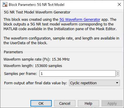
Similarly, the 5G NR Test Model block transmits standard-compliant NR-TM waveforms, as defined in TS 38.141-1. You can generate this block using the 5G Waveform Generator (5G Toolbox) app. The example also uses the InitFcn in the Model callbacks to store the NR-TM configuration available in the block user data in a Base Workspace variable, IntInfo. For more information about this block, see Waveform From Wireless Waveform Generator App (5G Toolbox).
To use a different HE SU waveform, open the WLAN Waveform Generator app, select the HE SU configuration, and export a new block. Similarly, to use a different NR-TM waveform, open the 5G Waveform Generator app, select the NR-TM configuration, and export a new block. For more information on how to generate and use such blocks, see Generate Wireless Waveform in Simulink Using App-Generated Block.
Alternatively, you can model an 802.11ax interferer by selecting Choice_HE in the Variant Source block. The model shifts the HE interferer so that it is not synchronized with the desired HE waveform.
Control the power of both waveforms by setting the HE Gain and Interferer Gain blocks. To cancel the transmission of the interferer, set the Gain parameter of the Interferer Gain block to 0.
The Sample-Rate Match block upsamples the waveform with lower sample rate to match the sample rate of the other waveform. The waveforms must have the same sample rate when combining the waveforms in the Multiband Combiner block. The Sample-Rate Match block also concatenates both waveforms horizontally, one column per waveform.
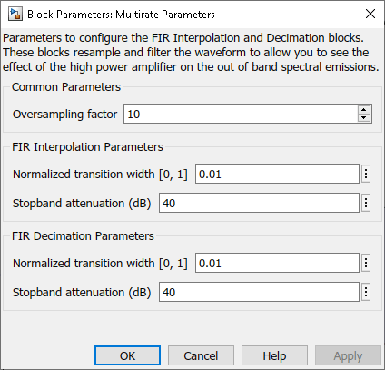
An FIR Interpolation block oversamples and filters the waveforms to show the effect of the nonlinear impairments on the adjacent channels. To capture at least fifth-order nonlinearities, oversample the combined bandwidth (both waveforms) by a factor of five. As the current combined bandwidth is 35 MHz (20 and 10 MHz bandwidths and a 20 MHz spacing between them), set an Oversampling factor of 10 to provide a sample rate of 200 MHz, which is around five times the combined bandwidth. You can set the Oversampling factor in the Multirate Parameters block, which provides an interface to configure the parameters of the FIR Interpolation and Decimation blocks.
The Multiband Combiner block frequency shifts and aggregates the oversampled waveforms. To measure the ACR, place the center frequency of the adjacent channel 20, 40, 80, or 160 MHz away from the center frequency of the desired signal, according to IEEE Std 802.11ax-2021. By default, the example centers the HE waveform at baseband (0 Hz) and sets the spacing between the HE and interfering waveforms to 20 MHz. You can adjust the center frequencies by specifying the Frequency offsets (Hz) parameter in the Multiband Combiner block. The ACR measurement is displayed in the ACR (dB) block.
Specify Simulation Time
Set the Stop Time value in the Simulink model to the time required to transmit and obtain the EVM results and constellation diagram of at least one packet. Considering the waveform configuration selected in the WLAN 802.11ax block, the packet transmission time in this example is 85.8 microseconds. As the filters in the FIR Interpolation, Decimation and Rate Conversion blocks introduce a delay, you can use the IdleTime parameter in the Mask Editor of the WLAN 802.11ax block to compensate for the delay.
RF Reception
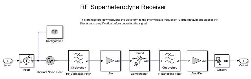
The RF Receiver Subsystem block is based on a superheterodyne receiver architecture. This architecture models the effects of downconverting the combined waveform to an intermediate frequency by characterizing these RF components:
RF and IF bandpass filters
Low noise amplifiers
Demodulator consisting of mixers, phase shifter, and local oscillator
set_param(modelName,'Open','off');
set_param([modelName '/RF Receiver'],'Open','on');
Use an Input Buffer block to send one sample at a time to the RF Receiver Subsystem block.
The Inport block inside the RF Receiver Subsystem block converts the combined Simulink complex baseband waveform into the RF Blockset Circuit Envelope simulation environment. You can vary the center frequency of the combined RF signal by modifying the Carrier frequency parameter of the Inport block. By default, the Carrier frequency parameter of the Inport block corresponds to the center frequency of the desired HE waveform and the carrier frequency of the NR waveform is located 20 MHz from the HE carrier. The Outport block converts the RF Blockset signal back into Simulink complex baseband.
You can configure the RF Receiver components by using the RF Receiver Subsystem block mask.
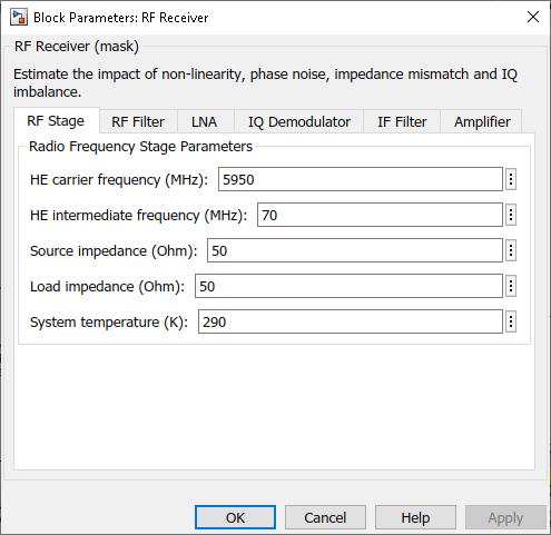
The RF Receiver Subsystem block models typical impairments, including:
Phase noise as an effect directly related to the thermal noise within the active devices of the oscillator
Amplifier nonlinearities due to DC power limitation when the amplifiers work in the saturation region
Impedance mismatch resulting in signal reflection or an inefficient power transfer
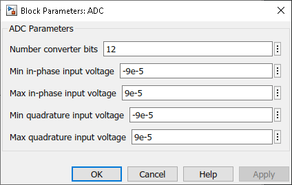
As the current RF Receiver Subsystem block configuration sends one sample at a time, the Output Buffer block (after the RF Receiver Subsystem block) collects all samples within the baseband HE waveform before sending the samples to the HE Demodulation and EVM Calculation block. At the output of the RF Receiver Subsystem block, the FIR Decimation and FIR Rate Conversion blocks downsample the waveform back to its original sampling rate. Additionally, the ADC Subsystem block digitizes the signal. You can modify the parameters of the blocks inside the ADC Subsystem block using its mask.
Baseband Waveform Reception
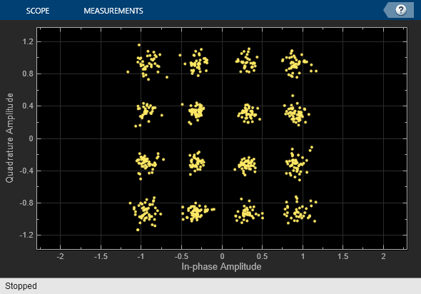
The HE Demodulation and EVM Calculation block recovers and plots the HE-Data symbols in the Constellation Diagram block by performing frequency and packet offset corrections, channel estimation, pilot phase tracking, OFDM demodulation, and equalization. This block performs these EVM measurements:
EVM per subcarrier (dB): EVM averaged over the allocated HE-Data symbols within a subcarrier
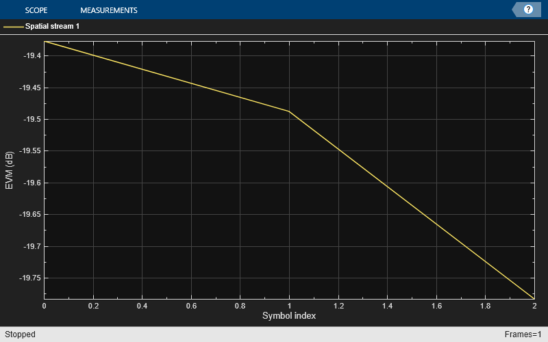
EVM per OFDM symbol (dB)
Overall EVM (dB and %): EVM averaged over all transmitted HE-Data symbols
This block also decodes each packet to recover the transmitted bits. The example compares the recovered bits to those transmitted for each packet to determine the packet error rate for the simulation duration by using the PER Calculation block.
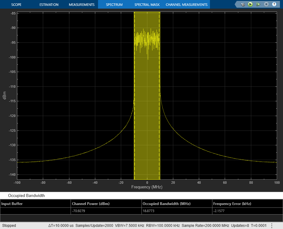
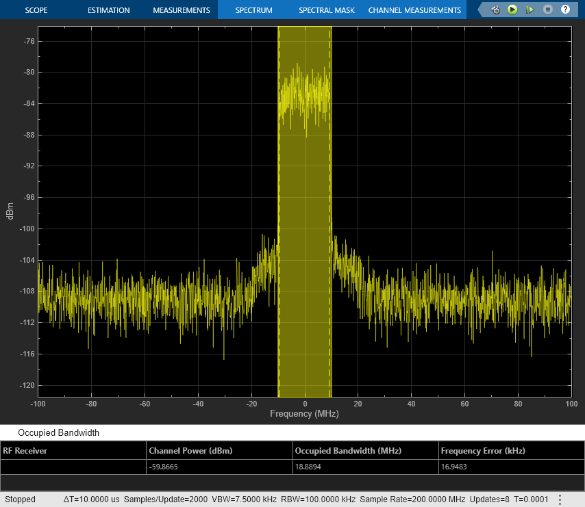
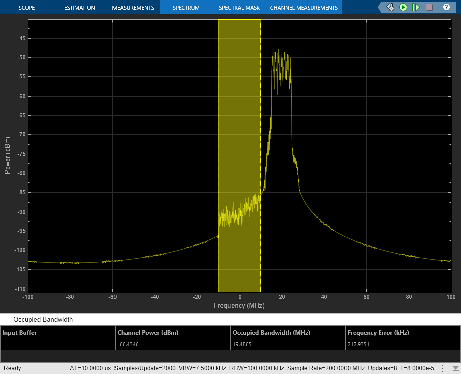
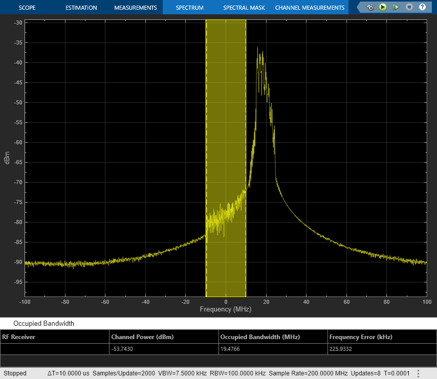
The ACR measurement is displayed in the ACR (dB) block. You can also measure the ACR by calculating the power difference between the Channel Power levels of each waveform in the Spectrum Analyzer Input block. To check the Channel Power levels of each waveform, set this configuration in the Spectrum Analyzer Input block:
The Span (Hz): must be the bandwidth of the waveform to measure. By default, the example sets this value to 20 MHz, which is the bandwidth of the desired HE waveform.
The CF (Hz): must be 0 for the desired HE waveform or the spacing between both waveforms (defined in the Multiband Combiner block) for the interferer. By default, the example sets this value to 0 Hz to measure the channel power of the desired waveform.
To measure ACR according to IEEE Std 802.11ax-2021, set the desired waveform power 3 dB above the rate-dependent sensitivity specified in Table 27-51 (-71 dBm for the default configuration) and adjust the power level of the interferer waveform to achieve a 10% PER for a PSDU length of 4096 octets.
Model Performance
To characterize the impact of the NR interference on the HE reception you can compare the EVM for two different cases: 1) without interference, for example, transmit only the HE waveform; and 2) with interference, for example, transmit both HE and NR waveforms. You can also measure the ACR in the second case.
Without NR interference (NR gain = 0). To eliminate the NR interference, set the Gain parameter of the Interferer Gain block to 0. To calculate the EVM and plot the constellation diagram, run the simulation to capture one packet (Stop Time equal to 85.5 microseconds for the default configuration).
set_param([modelName '/Interferer Gain'],'Gain','0');
sim(modelName);
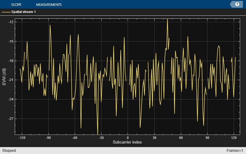
When you disable the interference, the overall EVM is around -20 dB.
With NR interference (NR gain = -37.72 dB). To activate the NR interference, set the Gain parameter of the Interferer Gain block to any value greater than 0. For example, in order to measure the ACR when the PER is approximately 10% for a PSDU length of 4096 octets, IEEE Std 802.11ax-2021, choose a gain value of around -30 dB and increase the APEP length. If you want to measure the PER for several packet transmissions, for example 100 packets, multiply the current Stop Time value by 100. By default, the example transmits one packet and sets the APEP length to 50 bytes.
set_param([modelName '/Interferer Gain'],'Gain','db2mag(-30)');
sim(modelName);
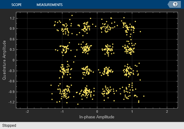
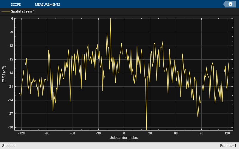
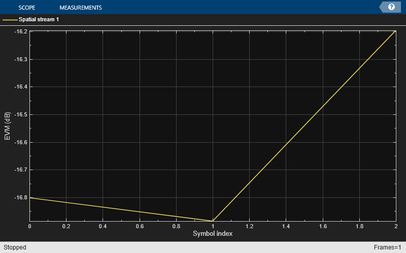
Compared to the case without interference, the constellation diagram is more distorted and the overall EVM is around -17 dB.
The ACR is around 38 dB. You can also measure the ACR when the interferer is an HE waveform. In this case, to measure the ACR when the PER is approximately 10% for a PSDU length of 4096 octets, IEEE Std 802.11ax-2021, set the Gain value of the Interferer block to around -72.4 dB.
Summary and Further Exploration
This example demonstrates how to model and test the reception of an HE waveform coexisting with an NR waveform or another HE waveform. The RF receiver consists of bandpass filters, amplifiers, and a demodulator. To evaluate the impact of the NR interference, the example modifies the gain of the NR waveform and performs EVM, PER, and ACR measurements. You can explore the impact of altering the RF impairments. For example:
Increase the phase noise by using Phase noise offset (Hz) and Phase noise level (dBc/Hz) parameters on the Demodulator tab of the RF Receiver Subsystem block.
Decrease the LO to RF isolation by using the LO to RF isolation (dB) parameter on the Demodulator tab of the RF Receiver Subsystem block.
This example configures the RF Receiver Subsystem block to work with the default values of the WLAN 802.11ax and 5G NR Test Model blocks and with the HE and NR carriers centered at 5950 MHz and 5970 MHz, respectively. These carriers are within the IEEE 802.11 HE frequency bands (between 1 GHz and 7.125 GHz) and the NR operating band n96, according to IEEE Std 802.11ax-2021 and TS 38.101-1, respectively. If you change the carrier frequencies or the waveform configurations, check if you need to update the parameters of the RF Receiver Subsystem block as these parameters have been selected to work for the default configuration of the example. For instance, a change in the HE carrier frequency requires revising the Passband frequencies and Stopband frequencies parameters of the RF Bandpass Filter block inside the RF Receiver. If you increase the waveform bandwidth, check if you need to update the Impulse response duration and Phase noise frequency offset (Hz) parameters of the Demodulator (RF Blockset) block. The phase noise offset determines the lower limit of the impulse response duration. If the phase noise frequency offset resolution is high for a given impulse response duration, a warning message appears, specifying the minimum duration suitable for the required resolution.
You can use this example as the basis for testing the coexistence between HE and NR or HE waveforms for different RF configurations. You can replace the RF Receiver Subsystem block with another RF subsystem and then configure the model accordingly.
You can also use this example as the basis for performing the coexistence tests defined in IEEE/ANSI C63.27-2017, the American National Standard for Evaluation of Wireless Coexistence. Examples of those tests are:
Wi-Fi devices operating in the 2.4 GHz ISM band (2.4 to 2.4835 GHz), where the unintended signals (or interferers) are 802.11n or LTE.
Wi-Fi devices operating in the 5 GHz UNII & ISM bands (5.15 to 5.85 GHz), where the unintended signal (or interferer) is 802.11n.
To transmit the 802.11n or LTE interferers, open the WLAN Waveform Generator app or the LTE Waveform Generator (LTE Toolbox) app, respectively, and export a new block. To change the frequency band, modify the HE carrier frequency (MHz) parameter in the RF Receiver Subsystem block mask. You can also place the adjacent unintended waveform at a different frequency by updating the Frequency offsets (Hz) parameter in the Multiband Combiner block.
Bibliography
3GPP TS 38.141-1. "NR; Base Station (BS) conformance testing Part 1: Conducted conformance testing." 3rd Generation Partnership Project; Technical Specification Group Radio Access Network.
IEEE Std 802.11ax™-2021. IEEE Standard for Information Technology - Telecommunications and Information Exchange between Systems - Local and Metropolitan Area Networks - Specific Requirements - Part 11: Wireless LAN Medium Access Control (MAC) and Physical Layer (PHY) Specifications - Amendment 1: Enhancements for High-Efficiency WLAN.
3GPP TS 38.101-1. "NR; User Equipment (UE) radio transmission and reception." 3rd Generation Partnership Project; Technical Specification Group Radio Access Network.
IEEE/ANSI C63.27-2017 - American National Standard for Evaluation of Wireless Coexistence