HDL Digital Automatic Gain Control for Single and Multicarrier Systems
This example shows how to implement a digital automatic gain control (AGC) for single and multicarrier systems using Simulink® blocks. These Simulink blocks are optimized for HDL code generation and hardware implementation.
The digital AGC module uses a feedback algorithm that adaptively adjusts the amplitude of a signal to achieve a constant average signal power at the output. This example shows how to use a digital AGC in a root-raised-cosine (RRC) pulse-shaping single-carrier system and in an orthogonal frequency division multiplexing (OFDM) multicarrier system with an additive white Gaussian noise (AWGN) channel and power attenuation.
Digital AGC Block Diagram
The Error Detector block detects errors by subtracting the computed output signal power from the desired output power. The Gain block multiplies the error with the step size of the AGC. The Integrator block continuously integrates the output of the Gain block. The Multiplier block multiplies the output of the integrator with the input to adjust the amplitude and generates the desired output power.

File Structure
This example uses these Simulink models and MATLAB® scripts.
DigitalAGCSCMCSystems— Comprises the single and multicarrier systems with digital AGC.digitalAGCDesignFIRFilter— Generates FIR filter coefficients required for the multicarrier system in theDigitalAGCSCMCSystemsmodel.digitalAGCVaryParam— Runs theDigitalAGCmodel. You can use this script to set the channel power gain and the AGC step size and desired output power.DigitalAGC— Comprises a constellation source, channel, and digital AGC. You can use this model to verify the output of the AGC for different parameter configurations.
Model Architecture
This figure shows the structure of the DigitalAGCSCMCSystems model. In the Constellation Symbol Source subsystem, you can set the constellation to BPSK, QPSK, 8-PSK, 16-APSK, 32-APSK, 16-QAM, 64-QAM, or 256-QAM to generate equally likely constellation symbols with unit average power. The Compute Power subsystem computes the power of the constellation symbols. The RRC Single-Carrier System treats the symbols as time-domain symbols and the OFDM Multicarrier System treats the symbols as frequency-domain subcarriers. The single-carrier and multicarrier systems generate a transmitter signal and display the computed signal power. The Channel subsystem adds white Gaussian noise and attenuate the transmit signal to generate a receive signal. The Digital Automatic Gain Control subsystem adjusts the input receiver signal power to a desired output power. The Power Calculator SC and Power Calculator MC subsystems compute the digital AGC output power from the single and multicarrier systems, respectively. The single and multicarrier systems recover the constellation symbols from the AGC output and align them with reference symbols. The EVM SC and EVM MC subsystems display the computed error vector magnitude (EVM) value for every 1000 symbols.

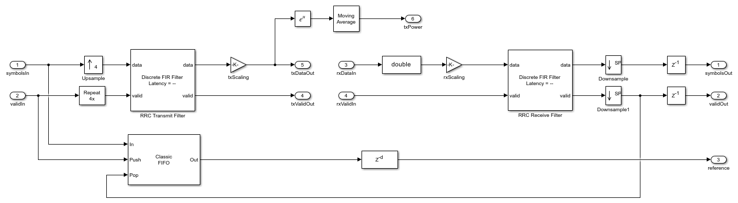
RRC Single-Carrier System
The RRC Transmit Filter and RRC Receive Filter are Discrete FIR Filter blocks with an RRC impulse response. You can set the RRC impulse response parameters in the RRC Single-Carrier System mask. The RRC Transmit Filter block pulse shapes the incoming symbols to generate a transmit signal. The transmit signal streams out for channel and digital AGC processing to generate a receive signal. The RRC Receive Filter block acts as a matched filter and filters the receive signal. The Downsample block downsamples the output of the RRC Receive Filter block to get the constellation symbols. The RRC Single-Carrier System is balanced with delays such that the samples after the downsample corresponds to the zero inter symbol interference (ISI) sample. The single-carrier system stores the reference symbols in a FIFO and align them with the output constellation symbols.
OFDM Multicarrier System
The Valid Generator subsystem generates a valid signal for a number of samples equal to the number of active subcarriers at an interval equal to the OFDM symbol length. The OFDM Modulator block modulates these subcarriers to generate OFDM symbols. The OFDM Transmit Filter is a Discrete FIR Filter block that filters the OFDM symbols to generate a transmit signal. The transmit signal streams out for channel and digital AGC processing to generate a receive signal. The OFDM Receive Filter is a Discrete FIR Filter block that filters the receive signal. The system discards the initial samples equal to the group delay of the two filters. The OFDM Demodulator block recovers the active subcarriers of each OFDM symbol. The system equalizes the active subcarriers with the combined frequency response of the transmit and receive filters. The group delay of the filters results in a time shift in the OFDM symbols, which is the same as the multiplication of complex exponential sinusoidal factors in the frequency domain. The system precomputes these sinusoidal factors and stored in an LUT. The system equalizes the OFDM demodulated samples obtained in frequency domain using the sinusoidal factors stored in the LUT. The system stores the reference subcarriers in a FIFO and align them with the equalized subcarriers.

EVM
The EVM SC and EVM MC subsystems compute the root mean squared (RMS) error between the output and the reference signal for single and multicarrier systems, respectively, for every 1000 symbols.
Run Model
This example contains two Simulink models.
To initialize and run the DigitalAGC model and plot the output, use the digitalAGCVaryParam script. You can modify the AGC step size, channel attenuation, or AGC desired output power variables in the script to check the working of a digital AGC.
To operate the Digital AGC in single and multicarrier systems, run the DigitalAGCSCMCSystems model. Perform these steps before running the model.
Set the
Constellation Symbol Sourcesubsystem to a required constellation for which you want to generate.Set the power gain of the
Channelsubsystem to a positive or negative value to increase or attenuate the signal power.Set the signal-to-noise ratio on the
Channelsubsystem to add white Gaussian noise to the signal.Set the single and multicarrier parameters in the RRC Single-Carrier System and the OFDM Multicarrier System, respectively.
The EVM SC and EVM MC subsystems compute the EVM of the single and multicarrier systems, respectively.
Results
You can modify the AGC desired output power, step size, and channel power gain in the digitalAGCVaryParam script and verify the results.
For desired output power values,  ,
,  ,
,  , and
, and  , see the results in this figure. The simulation output power is same as the desired output power in all the cases.

For step size values  ,
,  ,
,  and
and  , see the results in this figure. The more the step size the lesser the number of samples required to converge.

For channel power gain values  ,
,  ,
,  , and
, and  , see the results in this figure. The lesser the gain or more is the attenuation, more is the convergence time.

This figure shows the EVM plot for 30 dB channel attenuation for the default values of the SNR, constellation, single and multicarrier system.

Generate HDL Code
To generate HDL code, you must have an HDL Coder™ license. Use the makehdl and makehdltb functions to generate HDL code and a test bench for the Digital Automatic Gain Control subsystem. The test bench generation time depends on the simulation time.
You can synthesize the generated HDL code and target the Xilinx® Zynq®-7000 ZC706 evaluation board. The table shows post place and route resource usage results. The maximum frequency of operation is 216 MHz.
       Resources       Usage
    _______________    _____

    Slice LUT          1379
    Slice Registers    1562
    RAMB36             0
    RAMB18             0
    DSP48              10
