Frame-Based Video Pipeline
This example shows how to implement a video processing pipeline in MATLAB® using frame-based functions and generate HDL code from the design.
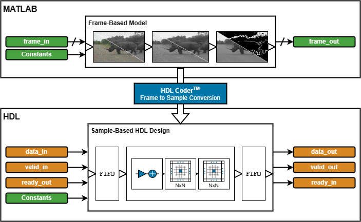
HDL Coder™ frame-to-sample optimization allows you to combine frame-based functions, element-wise operations, and custom neighborhood functions to rapidly prototype and develop algorithms for HDL code generation.
In this example, you refactor a frame-based MATLAB algorithm to use functions that support HDL code generation. Using a MATLAB testbench, you verify the refactored algorithm against the original. Then, you expand the design to add support for subsampled YCbCr data. Finally, you generate HDL code and an HDL testbench for the YCbCr-compatible video processing pipeline.
MATLAB Reference
The video processing pipeline removes noise and sharpens a video before detecting and overlaying edges.
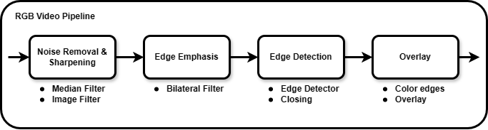
The noise removal step uses a median filter that does not further degrade the sharpness of the image.
The frame is then sharpened by using a 2-D image filter with an inverted Laplacian kernel.
Next, a bilateral filter smoothes the frame and emphasizes edges.
A Sobel edge detector and a morphological closing operation detect and improve the connectivity of edges.
Finally, the binary edge result is colored and overlaid onto the median-filtered RGB frames.
This code excerpt shows a uint8 Image Processing Toolbox™ implementation of the algorithm:
function [..] = FBVP_iptPipeline(..)

    % --- Setup
    % Sharpening filter coefficients
    hSharp = [ ...
        0 0 0; ...
        0 1 0; ...
        0 0 0] - fspecial('laplacian', 0.2);
    % Edge detection
    closingSE = strel('disk', 1);    % Morphological closing structuring element
    edgeColor = cat(3, 255, 0, 255); % 1-by-1-by-3 RGB triplet

    % --- Noise Removal & Sharpening
    median = zeros(size(frameIn), 'like', frameIn);
    for ii = 1 : 3
        median(:,:,ii) = medfilt2(frameIn(:,:,ii));             % 3-by-3 median filter
    end
    gray  = rgb2gray(median);                                   % RGB to grayscale
    sharp = imfilter(gray, hSharp);                             % Sharpening filter

    % --- Edge Emphasis
    bilateral = imbilatfilt(sharp, 36864, 0.9, NeighborhoodSize=5); % Bilateral filter

    % --- Edge Detection
    edges  = edge(bilateral, 'Sobel', 12/255);                  % Sobel edge detector
    closed = imclose(edges, closingSE);                         % Morphological closing

    % --- Overlay
    rgbEdges = uint8(closed .* edgeColor);                      % Color edges
    frameOut = median + rgbEdges;                               % Overlay
Frame-Based HDL Design
The first step to make the design suitable for HDL code generation is to convert the coefficients of the floating-point sharpening filter, hSharp, and RGB edge color, edgeColor, to fixed-point data type. You can represent hSharp using fixdt(1,16,12) and edgeColor using uint8. For help with data type conversion, see Manual Fixed-Point Conversion Best Practices (Fixed-Point Designer).
In the hardware-friendly algorithm, the image filter, hdlimfilter, and bilateral filter, hdlimbilatfilt, functions behave differently from their respective Image Processing Toolbox functions:
hdlimfilterrequires that the filter coefficients are in the range [-1, 1] and that the sum of the absolute coefficients is less than or equal to 1. Rescale the coefficients,hSharp, by dividing them by the maximum absolute value of the coefficients. Apply a gain to the output of the Image Filter to counteract the gain introduced by rescaling the coefficients.hdlimbilatfiltuses a look-up table (LUT) for hardware efficiency and so does not numerically matchimbilatfilt.hdlimbilatfiltalso requires intensity standard deviation rather than the degree of smoothing input used withimbilatfilt. Convert thedegreeOfSmoothinginput of theimbilatfiltfunction to theintensityStdDevinput for thehdlimbilatfiltfunction by dividing the square root ofdegreeOfSmoothingby the input word length.
The frame-based functions in this example do not support 3-D input and output. You can pass the RGB input to the median filter and the overlay stage by using a separate variable for each color channel. The top-level design function FBVP_rgbDUT.m also requires 2-D inputs and outputs.
This code excerpt shows the refactored algorithm:
function [..] = FBVP_rgbDUT(..)

    % --- Setup
    % Sharpening filter coefficients
    hSharp = ([ ...
        0 0 0; ...
        0 1 0; ...
        0 0 0] - fspecial('laplacian', 0.2)) ./ max(abs(fspecial('laplacian', 0.2)) + 1, [], "all");

    % Edge detection
    closingSE = strel("disk", 1);     % Morphological closing structuring element
    edgeColor = uint8([255, 0, 255]); % 1-by-3 RGB triplet

    % --- Noise Removal and Sharpening
    medianR  = hdlmedfilt2(RIn);                          % 3-by-3 median filter
    medianG  = hdlmedfilt2(GIn);
    medianB  = hdlmedfilt2(BIn);
    gray     = hdlrgb2gray(medianR, medianG, medianB);    % RGB to grayscale
    sharp    = hdlimfilter(gray, hSharp, 'Replicate', 0); % Sharpening filter
    sharp    = sharp * 4;                                 % Account for hSharp scaling

    % --- Edge Emphasis
    bilateral = hdlimbilatfilt(sharp, sqrt(36864)/2^8, 0.9, 5, 'Replicate', 0); % Bilateral filter

    % --- Edge Detection
    edges  = hdledge(bilateral, 'sobel', 12);             % Sobel edge detector
    closed = hdlimclose(edges, closingSE.Neighborhood);   % Morphological closing

    % --- Overlay
    closedUint = uint8(closed);                           % Color edges
    edgesR = closedUint * edgeColor(1);
    edgesG = closedUint * edgeColor(2);
    edgesB = closedUint * edgeColor(3);

    ROut = medianR + edgesR;                              % Overlay
    GOut = medianG + edgesG;
    BOut = medianB + edgesB;
Simulation
To verify the refactored code and fixed-point conversion, create a testbench to compare the reference algorithm and hardware design. Because of hardware optimization of the algorithms, the HDL-compatible functions can differ from the Image Processing Toolbox functions. A best practice when developing or adapting your own algorithms for hardware is to create a testbench and iteratively refactor your algorithm.
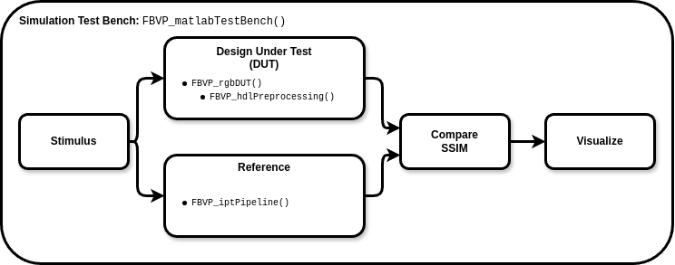
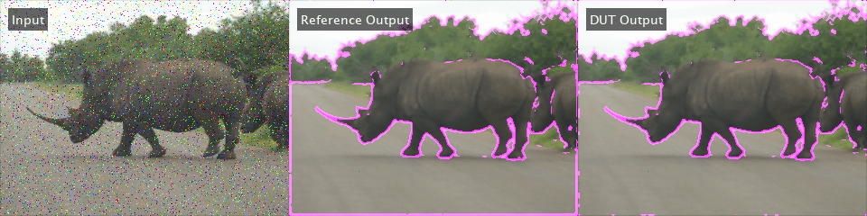
In the testbench, FBVP_matlabTestBench.m, the videoIn object reads frames from a video source, and the imfilter and imnoise functions apply a blur effect and introduce salt and pepper noise. The testbench calls the design under test (DUT), FrameBasedVideoPipelineMATLABDesign.m, to process each frame. The reference design, FBVP_iptPipeline.m, performs the same operations as the DUT using Image Processing Toolbox functions. The testbench compares the DUT and reference frame by calculating the Structural SIMilarity (SSIM) index and verifying that the index exceeds the minimum threshold. The viewer object displays the corrupted input frame, reference output, and DUT output. When the testbench is finished running, it displays the processed frame rate in the Command Window.
function [..] = FBVP_matlabTestBench(..)

    tic;
    for ii = 1 : numFrames
        % --- Stimulus
        frameIn(:) = videoIn.readFrame;                               % Source frame
        frameIn(:) = imfilter(frameIn, fspecial("gaussian", 3, 0.5)); % Gaussian blur
        frameIn(:) = imnoise(frameIn, "salt & pepper");               % Salt and pepper noise

        % --- Design Under Test (DUT)
        % Exercise DUT
        [R, G, B] = FBVP_rgbDUT(frameIn(:,:,1), frameIn(:,:,2), frameIn(:,:,3));
        frameOut = cat(3, R, G, B);

        % --- Reference
        frameReference = FBVP_iptPipeline(frameIn);

        % --- Compare
        frameSSIM(:) = ssim(frameReference, frameOut);
        if frameSSIM < ssimThreshold
            fprintf("frame #%u: reference and design output Structural SIMilarity (SSIM) index %.3g%% is less than the %.3g%% threshold.\n", ...
                ii, 100 * frameSSIM, 100 * ssimThreshold);
            return;
        end

        % --- Visualize
        frameIn        = insertText(frameIn,        [10 10], {'Input'},            FontSize=14, FontColor=[1 1 1], TextBoxColor=[0 0 0]);
        frameReference = insertText(frameReference, [10 10], {'Reference Output'}, FontSize=14, FontColor=[1 1 1], TextBoxColor=[0 0 0]);
        frameOut       = insertText(frameOut,       [10 10], {'DUT Output'},       FontSize=14, FontColor=[1 1 1], TextBoxColor=[0 0 0]);

        viewer(cat(2, frameIn, frameReference, frameOut));
    end
    t = toc;

    fprintf('\n%u frames have been processed in %.2f seconds.\n', numFrames, t);
    fprintf('Average frame rate is %.2f frames/second.\n', numFrames/t);
To enable MEX generation of the testbench, functions that do not support C code generation such as fprintf must be declared as extrinsic. Extrinsic functions are excluded from MEX generation and are executed using interpreted mode.
To simulate the design, generate MEX of the MATLAB testbench, FBVP_matlabTestBench.m, and execute it:
codegen("FBVP_matlabTestBench.m");Code generation successful.
FBVP_matlabTestBench_mex;
100 frames have been processed in 14.70 seconds.
Average frame rate is 6.80 frames/second.
Visually inspect the DUT and reference output and verify that the testbench completes successfully. The testbench has passed if all frames exceed the SSIM threshold and the final frame rate displays in the Command Window.
Debugging simulations with large frame sizes is impractical in interpreted mode due to long simulation time. However, debugging a MEX simulation is challenging due to lack of debug access into the code. To avoid these scenarios, a best practice is to develop and verify the algorithm and testbench using a thumbnail frame size. In most cases, the HDL-targeted design can be implemented with no dependence on frame size. In addition to using smaller frame sizes, when refactoring from an existing reference design, you can make small iterative changes for faster identification of errors and targeted debugging. Once you are confident that the design and testbench are working correctly, increase the frame size in the testbench and use MATLAB Coder™ tools to accelerate the simulation. Increasing the frame size in the testbench requires only minor changes.
Chrominance Preprocessing and Postprocessing
Some video processing hardware uses a subsampled chrominance-based color space, such as 4:2:2 YCbCr. To deploy an RGB-based algorithm to this type of hardware, you must perform color space conversion and chroma resampling at the input and output of the algorithm.
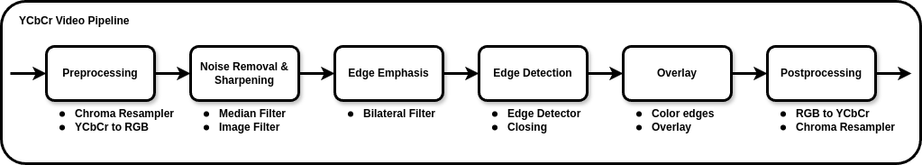
In this section, you add YCbCr 4:2:2 support to the HDL-compatible MATLAB design. The design function FrameBasedVideoPipelineHDLDesign.m includes the preprocessing and postprocessing stages. The preprocessing stage uses hdlresmplchroma to resample the input YCbCr 4:2:2 to YCbCr 4:4:4, allowing for conversion to RGB using hdlycbcr2rgb. The hdlrgb2ycbcr function converts the output of the algorithm back to YCbCr, and the chroma components are resampled from 4:4:4 to 4:2:2 to produce the final YCbCr 4:2:2 output.
This code excerpt shows the preprocessing and postprocessing stages.
function [..] = FBVP_ycbcrDUT(..)

    % --- Setup

    % --- Preprocessing (YCbCr 4:2:2 I/O Only)
    [Y, Cb, Cr] = hdlresmplchroma(Y, Cb, Cr);                                       % 4:2:2 to 4:4:4
    [R, G,  B ] = hdlycbcr2rgb(Y, Cb, Cr);                                          % YCbCr to RGB

    % --- Noise Removal and Sharpening...
    % --- Emphasize Edges...
    % --- Edge Detection...
    % --- Edge Overlay...

    % --- Postprocessing (YCbCr 4:2:2 I/O Only)
    [YOut, CbOut, CrOut] = hdlrgb2ycbcr(R, G, B);                                   % RGB to YCbCr
    [YOut, CbOut, CrOut] = hdlResampleChroma444To422FixedPoint(YOut, CbOut, CrOut); % 4:4:4 to 4:2:2
To validate the pre- and postprocessing stages, you can also enhance the reference design, FBVP_iptPipeline.m, to accept YCbCr 4:2:2 inputs by using the rgb2ycbcr and imadjust Image Processing Toolbox functions with a custom chroma resampling function or the vision.ChromaResampler Computer Vision Toolbox™ System object. This example does not show the enhanced reference design.
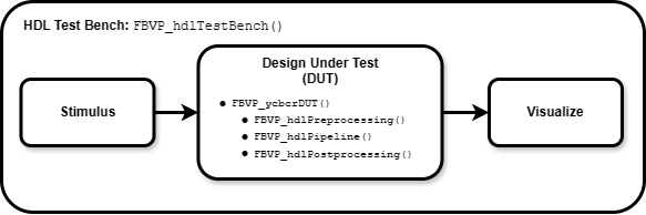
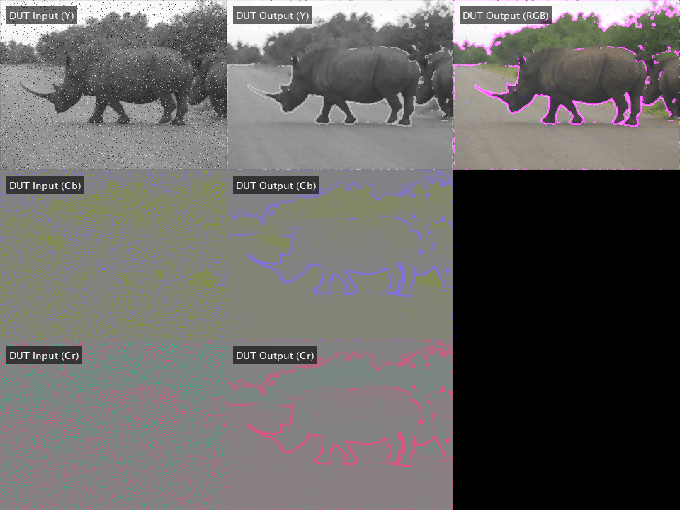
You can use an HDL testbench to verify the preprocessing, postprocessing, and generated HDL code. The HDL testbench, FBVP_hdlTestBench.m, is derived from the MATLAB testbench. The HDL testbench converts the corrupted input video frame from the RGB to YCbCr color space, and subsamples the chroma components to model the expected AXI-Stream input. The testbench calls the HDL DUT, FBVP_ycbcrDUT.m, to process each YCbCr 4:2:2 frame. The viewer object displays the YCbCr input, DUT output, and an RGB version of the DUT output.
To simulate the HDL design, generate MEX of the HDL testbench, FBVP_hdlTestBench.m, and call it in MATLAB.
codegen("FBVP_hdlTestBench.m");Code generation successful.
FBVP_hdlTestBench_mex;
HDL Code Generation and Verification
Once your design is working in simulation, use HDL Coder to generate HDL code for the FrameBasedVideoPipelineHDLDesign function.
Generating HDL using HDL Coder frame-to-sample optimization generates an entity with I/O suited for AXI-Stream interfaces and provides an input and output FIFO for memory contention and backpressure. You can configure the size of the FIFOs in the HDL Coder settings.
Use the hdlsetuptoolpath (HDL Coder) function for configuring synthesis tools and the vsim or nclaunch (HDL Verifier™) functions to configure HDL simulators.
Programmatic Code Generation and Simulation
Create an HDL Coder configuration object, hdlcfg, which generates HDL code and an HDL testbench, and simulates the generate code using ModelSim. To enable the frame-to-sample optimization, set the FrameToSampleConversion property of the coder.Hdlconfig object to true. For details, see coder.HdlConfig (HDL Coder).
% Default HDL config
hdlcfg = coder.config('hdl');

% Sources
hdlcfg.DesignFunctionName = "FBVP_ycbcrDUT.m";
hdlcfg.TestBenchName      = "FBVP_hdlTestBench.m";

% Enable testbench generation and simulation
hdlcfg.GenerateHDLTestBench  = true;
hdlcfg.SimulateGeneratedCode = true;

% Enable frame-to-sample conversion
hdlcfg.FrameToSampleConversion = true;

% DUT argument prototype
frameIn = VideoReader("rhinos.avi").readFrame;

% Generate HDL and HDL testbench, then simulate
codegen -config hdlcfg -args {frameIn(:,:,1), frameIn(:,:,2), frameIn(:,:,3)}
Graphical Interface Code Generation and Simulation
Create a new HDL Coder project.
coder -hdlcoder -new FrameBasedVideoPipelineProject
Add the file FBVP_ycbcrDUT.m to the project as the MATLAB function and FBVP_hdlTestBench.m as the MATLAB testbench.
For a tutorial on using MATLAB HDL Coder projects, see Generate HDL Code from MATLAB Algorithms (HDL Coder).
Open the Workflow Advisor and enable the frame-to-sample optimization.
Under HDL Code Generation, on the Frame to Sample Conversion tab, select Enable frame to sample conversion.
Right-click the Code Generation step. Choose the option Run to selected task to run all the steps from the beginning through HDL code generation.
Examine the generated HDL code by clicking the links in the log window.
Next, enable HDL testbench generation and simulation. Under Verification - Verify with HDL Test Bench, select the Generate test bench and Simulate generated test bench options. Right-click the Verification - Verify with HDL Test Bench step. Choose the option Run to selected task to run all the required steps from the beginning through simulation of the generated HDL code.
Resources
The design was synthesized and put through place and route on an AMD Zynq® Ultrascale+™ MPSoC ZCU102.
Resource | Usage | Usage (%) |
LUT | |
|
LUTRAM | |
|
FF | |
|
BRAM | |
|
DSP | |
|
Fmax | |
|
When configured for a 1080p input, the design achieves the required timing constraints for operating at 60 frames per second. The generated HDL code includes discrete entities for any frame-based function that uses hdl.npufun or hdl.iteratorfun. The frame-based Vision HDL Toolbox™ functions, hdlrgb2gray, hdlrgb2ycbcr, and hdlycbcr2rgb, use these custom neighborhood functions, and so each becomes an entity inside the DUT entity.
See Also
You can use the design in this example as a MATLAB Function block in Simulink®. For details, see the Frame-Based Video Pipeline in Simulink example.