キャリブレートされたカメラによる平面オブジェクトの測定
この例では、キャリブレートされた単一のカメラを使ってコインの直径をワールド単位で測定する方法を説明します。
概要
この例では、カメラをキャリブレーションし、それを使ってコインなどの平面オブジェクトのサイズを測定する方法を説明します。この方法の応用例として、品質管理を目的とした、コンベヤー ベルト上の部品の測定が挙げられます。
カメラのキャリブレーション
カメラのキャリブレーションは、レンズとイメージ センサーのパラメーターを推定するプロセスです。これらのパラメーターは、カメラで撮影したオブジェクトを測定するために必要です。この例では、プログラミングを使ってカメラのキャリブレーションを行う方法を説明します。別の方法として、単一カメラ キャリブレーター アプリの使用アプリを使用してカメラをキャリブレーションすることもできます。
カメラのキャリブレーションを行うには、まずキャリブレーション パターンの複数のイメージを異なる角度から撮影する必要があります。一般的なキャリブレーション パターンは、1 辺の方向に白黒の正方形が偶数個含まれ、もう 1 辺の方向には奇数個の正方形が含まれる、非対称のチェッカーボードです。
パターンは平らな面に貼り付けられ、カメラからの距離を測定対象のオブジェクトとほぼ同じにしなければなりません。正方形のサイズは、たとえばミリメートルなどのワールド単位で、できるだけ正確に測定しなければなりません。この例ではパターンのイメージを 9 つ使用しますが、実際に正確なキャリブレーションを行うには 10 ~ 20 個のイメージを使用することが推奨されます。
キャリブレーション イメージの準備
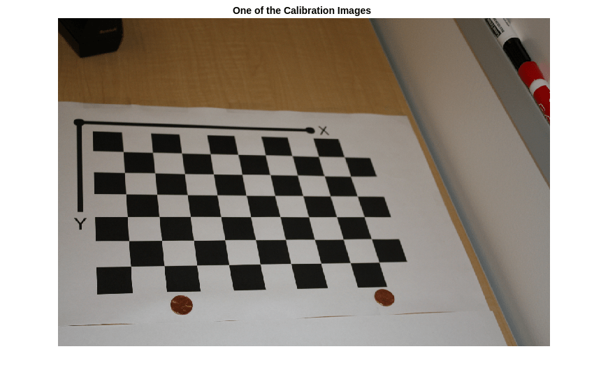
一連のキャリブレーション イメージを作成します。
images = imageDatastore(fullfile(toolboxdir("vision"),"visiondata",...
    "calibration","slr"));
files = images.Files;

% Display one of the calibration images
I = imread(files{1});
figure
imshow(I)
title("One of the Calibration Images")
カメラ パラメーターの推定
% Detect the checkerboard corners in the images.
[imagePoints, patternDims] = detectCheckerboardPoints(files);

% Generate the world coordinates of the checkerboard corners in the
% pattern-centric coordinate system, with the upper-left corner at (0,0).
squareSize = 29; % in millimeters
worldPoints = patternWorldPoints("checkerboard", patternDims, squareSize);

% Calibrate the camera.
imageSize = size(I,1:2);
cameraParams = estimateCameraParameters(imagePoints, worldPoints, ImageSize=imageSize);

% Evaluate calibration accuracy.
figure
showReprojectionErrors(cameraParams)
title("Reprojection Errors")

棒グラフはキャリブレーションの精度を示しています。それぞれのバーは、対応するキャリブレーション イメージの平均再投影誤差を表します。再投影誤差は、イメージ内で検出されたコーナー ポイントと、イメージに投影された対応する理想的なワールド ポイントとの距離です。
測定するオブジェクトのイメージの読み取り
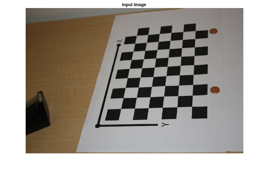
測定対象のオブジェクトを含むイメージを読み込みます。このイメージはキャリブレーション パターンを含んでおり、そのパターンは、測定するオブジェクトと同じ平面にあります。この例では、パターンとコインの両方が同じテーブルの上に置かれています。
別の方法として、パターンを含むイメージと測定対象のオブジェクトを含むイメージという、2 つの異なるイメージを使用することもできます。その場合もオブジェクトとパターンは同じ平面上になければなりません。また、イメージをまったく同一の視点から撮影する必要があるので、カメラは固定されていなければなりません。
imOrig = imread(fullfile(matlabroot, "toolbox", "vision", "visiondata", ...
        "calibration", "slr", "image9.jpg"));
figure
imshow(imOrig)
title("Input Image")
イメージの歪み補正
cameraParameters オブジェクトを使用して、イメージからレンズ歪みを除去します。これは正確な測定を行うために必要です。
% Since the lens introduced little distortion, use 'full' output view to illustrate that
% the image was undistorted. If we used the default 'same' option, it would be difficult
% to notice any difference when compared to the original image. Notice the small black borders.
[im, newIntrinsics] = undistortImage(imOrig, cameraParams, OutputView="full");
figure
imshow(im)
title("Undistorted Image")

このイメージでのレンズ歪みはごくわずかであることに注意してください。広角レンズや低品質の Web カメラを使用する場合には、歪み補正の手順がより重要となります。
コインのセグメント化
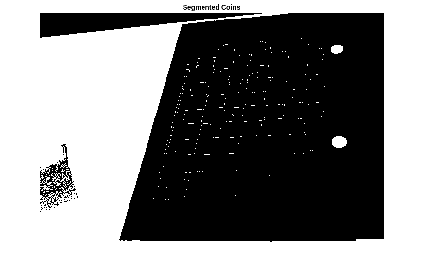
ここでは、色彩のついたコインが白を背景として置かれています。イメージの HSV 表現の彩度成分を使用してコインを切り出します。
% Convert the image to the HSV color space.
imHSV = rgb2hsv(im);

% Get the saturation channel.
saturation = imHSV(:, :, 2);

% Threshold the image
t = graythresh(saturation);
imCoin = (saturation > t);

figure
imshow(imCoin)
title("Segmented Coins")
コインの検出
セグメント化されたイメージにある 2 つの最大の連結要素がコインに対応すると仮定できます。
% Find connected components.
blobAnalysis = vision.BlobAnalysis(AreaOutputPort=true,...
    CentroidOutputPort=false,...
    BoundingBoxOutputPort=true,...
    MinimumBlobArea=200, ExcludeBorderBlobs=true);
[areas, boxes] = step(blobAnalysis, imCoin);

% Sort connected components in descending order by area
[~, idx] = sort(areas, "Descend");

% Get the two largest components.
boxes = double(boxes(idx(1:2), :));

% Reduce the size of the image for display.
scale = 0.25;
imDetectedCoins = imresize(im, scale);

% Insert labels for the coins.
imDetectedCoins = insertObjectAnnotation(imDetectedCoins, "rectangle", ...
    scale*boxes, "penny");
figure
imshow(imDetectedCoins)
title("Detected Coins")

外部パラメーターの計算
イメージ座標の点をワールド座標の点にマッピングするには、キャリブレーション パターンを基準としてカメラの回転と並進を計算する必要があります。関数 estimateExtrinsics ではレンズ歪みがないと仮定する点に注意してください。ここでは、undistortImageを使って既に歪み補正されたイメージ内で imagePoints が検出されています。
% Detect the checkerboard.
[imagePoints, patternDims] = detectCheckerboardPoints(im);

% Extract camera intrinsics.
camIntrinsics = cameraParams.Intrinsics;

% Adjust the imagePoints so that they are expressed in the coordinate system
% used in the original image, before it was undistorted.  This adjustment
% makes it compatible with the cameraParameters object computed for the original image.
newOrigin = camIntrinsics.PrincipalPoint - newIntrinsics.PrincipalPoint;
imagePoints = imagePoints + newOrigin; % adds newOrigin to every row of imagePoints

% Compute extrinsic parameters of the camera.
camExtrinsics = estimateExtrinsics(imagePoints, worldPoints, camIntrinsics);
最初のコインの測定
最初のコインを測定するには、境界ボックスの左上と右上のコーナーをワールド座標に変換します。そして、その間のユークリッド距離をミリメートル単位で計算します。アメリカの 1 セント硬貨の実際の直径は 19.05 mm であることに注意してください。
% Adjust upper left corners of bounding boxes for coordinate system shift
% caused by undistortImage with output view of 'full'. This would not be
% needed if the output was 'same'. The adjustment makes the points compatible
% with the cameraParameters of the original image.
boxes = boxes + [newOrigin, 0, 0]; % zero padding is added for width and height

% Get the top-left and the top-right corners.
box1 = double(boxes(1, :));
imagePoints1 = [box1(1:2); ...
                box1(1) + box1(3), box1(2)];

% Get the world coordinates of the corners
worldPoints1 = img2world2d(imagePoints1, camExtrinsics, camIntrinsics);

% Compute the diameter of the coin in millimeters.
d = worldPoints1(2, :) - worldPoints1(1, :);
diameterInMillimeters = hypot(d(1), d(2));
fprintf("Measured diameter of one penny = %0.2f mm\n", diameterInMillimeters);
Measured diameter of one penny = 19.00 mm
2 番目のコインの測定
2 番目のコインを最初のコインと同じ方法で測定します。
% Get the top-left and the top-right corners.
box2 = double(boxes(2, :));
imagePoints2 = [box2(1:2); ...
                box2(1) + box2(3), box2(2)];

% Apply the inverse transformation from image to world
worldPoints2 = img2world2d(imagePoints2, camExtrinsics, camIntrinsics);

% Compute the diameter of the coin in millimeters.
d = worldPoints2(2, :) - worldPoints2(1, :);
diameterInMillimeters = hypot(d(1), d(2));
fprintf("Measured diameter of the other penny = %0.2f mm\n", diameterInMillimeters);
Measured diameter of the other penny = 18.85 mm
最初のコインまでの距離の測定
コインのサイズだけでなく、カメラからコインまでの距離も測定できます。
% Compute the center of the first coin in the image.
center1_image = box1(1:2) + box1(3:4)/2;

% Convert to world coordinates.
center1_world  = img2world2d(center1_image, camExtrinsics, camIntrinsics);

% Remember to add the 0 z-coordinate.
center1_world = [center1_world 0];

% Compute the distance to the camera.
cameraPose = extr2pose(camExtrinsics);
cameraLocation = cameraPose.Translation;
distanceToCamera = norm(center1_world - cameraLocation);
fprintf("Distance from the camera to the first penny = %0.2f mm\n", ...
    distanceToCamera);
Distance from the camera to the first penny = 719.52 mm
まとめ
この例では、キャリブレートされたカメラを使用して平面オブジェクトを測定する方法を説明しました。測定値が誤差 0.2 mm 以内の精度であったことに注意してください。
参考文献
[1] Z. Zhang. A flexible new technique for camera calibration. IEEE Transactions on Pattern Analysis and Machine Intelligence, 22(11):1330-1334, 2000.