Simulate Sequence Diagrams for Traffic Light Example
This demonstrates how to simulate a System Composer™ architecture model of a traffic light and verify that the model simulation results match the interactions within the sequence diagrams of the model. The example model uses blocks from Stateflow®. If you do not have a Stateflow license, you can open and simulate the model but only make basic changes such as modifying block parameters.
This traffic light example uses sequence diagrams to describe the process of pedestrians crossing an intersection.
The traffic signal cycles from red to green to yellow.
When the pedestrian crossing button is pressed, if the traffic signal is green, the traffic signal transitions from yellow to red for a limited time.
The pedestrians cross while the walk signal is active.
Open the model.
model = systemcomposer.openModel("TLExample");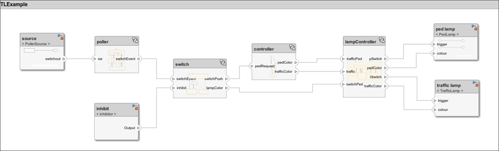
Open the Architecture Views Gallery to view the sequence diagrams.
openViews(model);
Simulate Inhibit Sequence Diagram
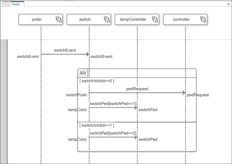
Open the Inhibit sequence diagram. In the View Browser of the Architecture Views Gallery, select the Inhibit sequence diagram.
 z
z
You can step through the simulation of a sequence diagram using the Next Message button in the toolstrip.
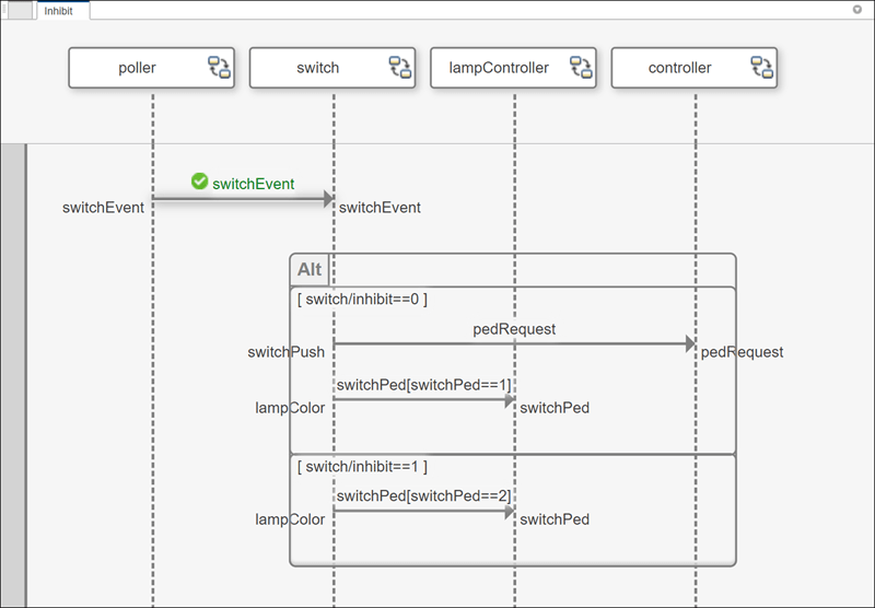
To simulate the first message, click the Next Message button in the toolstrip. Observe a green check mark which indicates that the message was validated during execution. When the message event
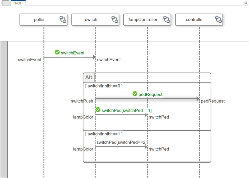
switchEventoccurs, theswitchlifeline activates.Click the Continue button to simulate the diagram to completion. Observe green check marks on the messages of the first operand of the
Altfragment. Since theinhibitflag is equal to 0, the first operand of theAltfragment activates. Theswitchlifeline sends a message to thecontrollerlifeline to indicate that a pedestrian pushed the crossing button. Then theswitchlifeline sends a message to thelampControllerlifeline to request to stop traffic and allow the pedestrians to cross the intersection.
Simulate PressDetection Sequence Diagram Programmatically
Open the PressDetection sequence diagram. In the View Browser, select the PressDetection sequence diagram.
You can programmatically simulate a sequence diagram using a Simulink.SimulationInput object for the sim function. The ObservedSequenceDiagrams model configuration parameter specifies which sequence diagram to simulate. To specify which sequence diagram to simulate, set the ObservedSequenceDiagrams model parameter for the simulation.
simIn = Simulink.SimulationInput("TLExample");
simIn = setModelParameter(simIn,ObservedSequenceDiagrams="PressDetection",...
    ObservedSequenceDiagramsOut="sequenceDiagramOutput");
simOut = sim(simIn);
ObservedSequenceDiagramsOut is a property of the Simulink.SimulationOutput object captured in simOut. The object contains these properties:
Name: Name of the sequence diagram being simulated.Completed: Whether the simulation was completed.NumErrors: Number of errors found, which counts the number of red exclamation marks next to messages and duration constraints in your sequence diagram after simulation. The red marks indicate that the message triggers were satisfied, but the constraints were not met.
For ease of use, you can rename the optional ObservedSequenceDiagramsOut parameter to sequenceDiagramOutput, or any valid MATLAB® variable name.
sequenceDiagramOut = simOut.sequenceDiagramOutput
sequenceDiagramOut = struct with fields:
         Name: 'PressDetection'
    Completed: 1
    NumErrors: 0
Messages where the trigger is satisfied and the constraints are met turn green with a check mark. Since all message constraints are met, the number of errors is 0.
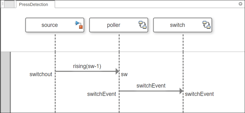
When a pedestrian presses the crossing button, the value of the signal sw rises to 1. When this action happens, the poller lifeline sends the message switchEvent to the switch lifeline. This action alerts the switch lifeline that a pedestrian is waiting so the switch lifeline can alert the controller lifeline. The traffic light then turns red to stop traffic, and the walk signal turns on.
Simulate and Detect Errors with PedestrianCross Sequence Diagram
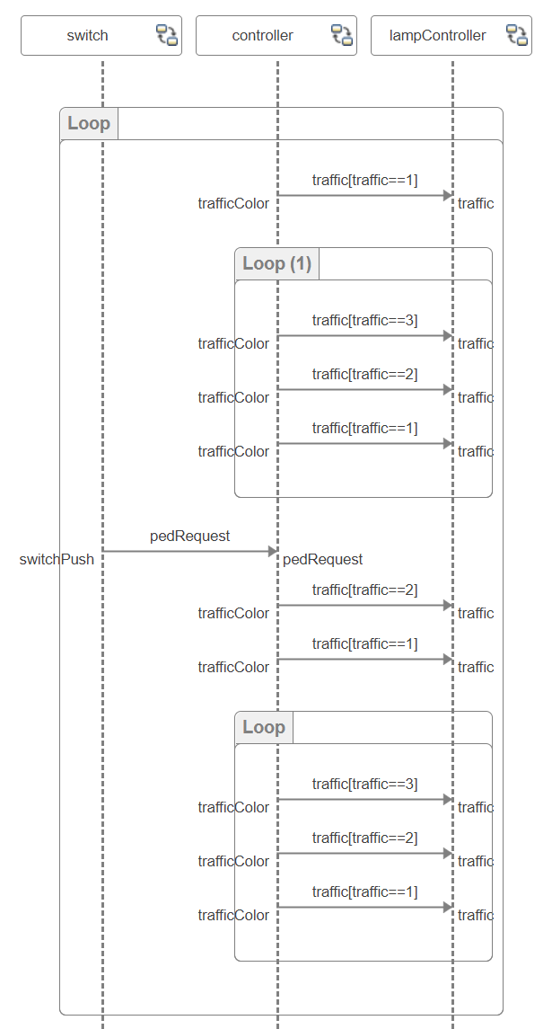
Open the PedestrianCross sequence diagram. In the View Browser, select the PedestrianCross sequence diagram.

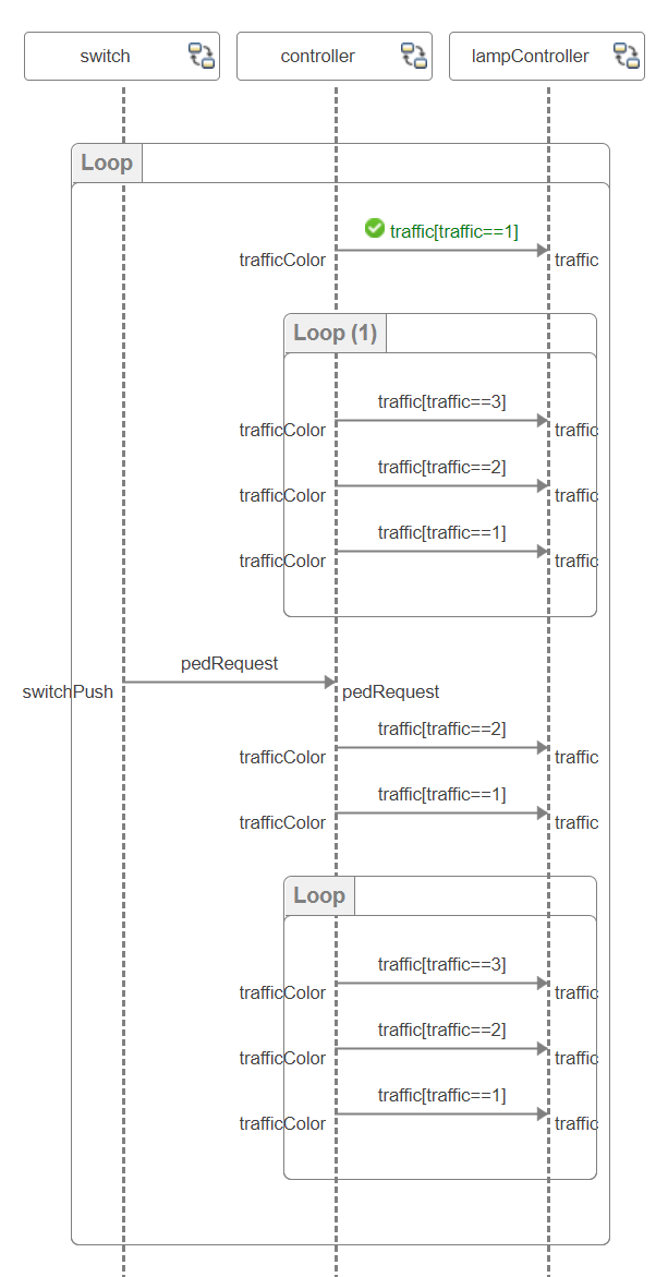
You can simulate a sequence diagram using the Run button in the toolstrip. Click the Run button to simulate the diagram to completion.
Observe green check marks on the messages. You can use the Sequence Viewer to observe the simulation events as they occur in the model as the sequence diagram describes what is expected to occur. To open the Sequence Viewer, on the toolstrip, in the Simulation tab, click the Sequence Viewer option.
View the corresponding message events for the pedestrian crossing messages in the Sequence Viewer.
From the Sequence Viewer, you can observe these simulation events:
The pedestrian crossing button was pushed.
The traffic light completes one loop from green (
traffic(3)) to yellow (traffic(2)) to red (traffic(1)) again.The pedestrian crossing signal allows the pedestrians cross by turning the traffic light red.
After the traffic light is red, the pedestrian crossing signal turns green (
trafficPed(3)).
You can use sequence diagrams to detect errors and inconsistencies between expected behavior and observed behavior. When you simulate your sequence diagrams, if an error is detected, the message expression or duration constraint expression turns red with a warning icon.
Although the PedestrianCross sequence diagram simulated as expected, you can introduce an error on purpose to observe this behavior.
Return to the
PedestrianCrosssequence diagram.To edit the duration constraint expression, double-click the duration constraint with expression
1 < t < 3sec.Introduce an error into the sequence diagram execution by changing the expression to
t < 1msec.Click Clear Results to clear the green check marks and reset sequence diagram execution.
Click Run to simulate the
PedestrianCrosssequence diagram again.

Observe an error is detected during simulation related to the duration constraint on the first message from the switch lifeline to the controller lifeline. The duration constraint expression t < 1msec specified by the sequence diagram is not met by the model execution and therefore detected as an error.
From the Sequence Viewer, you can observe that the switch component sends the pedRequest message around 11.2sec and the controller component receives the message around 14.1sec. Based on this observed time from model execution, the duration constraint with expression t > 1msec errors.

You can use sequence diagrams throughout the design process to verify that the model simulation results match the interactions within the sequence diagrams of the model. Iteratively check consistency between your architecture and the corresponding sequence diagrams.