Create Tabbed Dashboard Panels
A dashboard panel floats above the model canvas and follows you through the model hierarchy. Using panels, you can monitor signals, tune parameters, and debug from anywhere in your model without adding collections of dashboard blocks throughout the model.
You can use panels to model real dashboards, for example, the dashboard in your car. To model displays and controls on the panel, such as gauges, lamps, knobs, buttons, and switches, you can promote blocks to the panel from the Dashboard library, the Customizable Blocks library, and the Aerospace Blockset library. For information about how to create, populate, edit, and manage the visibility of panels, see Getting Started with Dashboard Panels.
By default, the first panel you create in a model has a single tab. To model multiple dashboards, you can make multiple panels or add tabs to a panel.

You can rename each tab. The same editing options available for a panels with a single tab are available for panels with multiple tabs. However, when you edit a panel with multiple tabs, the edits are only applied to the selected tab. For example, when you enter edit mode and drag a corner of a panel, only the selected tab of that panel is resized.
You can also customize the tab layout:
Change the order of tabs in a panel.
Detach tabs from a panel.
Attach tabs from one panel to a different panel.
Convert freestanding panels into tabs of another panel.
You can switch which tab a panel displays using the simulink.dashboard.switchPanelTab function.
This example shows you how to create tabs, rename tabs, reorder tabs, detach a tab from a panel, and attach a tab to another panel.
Open Example Model
In this example, you create tabbed panels and change their arrangement. The panels you create contain dashboard blocks for monitoring and testing a fuel control system.
Open the sldemo_fuelsys model from the Model Fault-Tolerant Fuel Control System
example.
openExample('simulink_automotive/ModelingAFaultTolerantFuelControlSystemExample')The sldemo_fuelsys model has a Dashboard subsystem
that contains controls and indicators for interactively simulating the model. Navigate
inside the Dashboard subsystem.
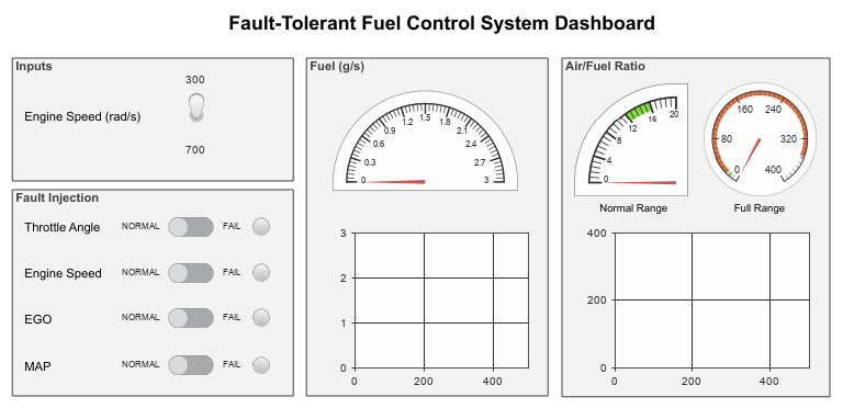
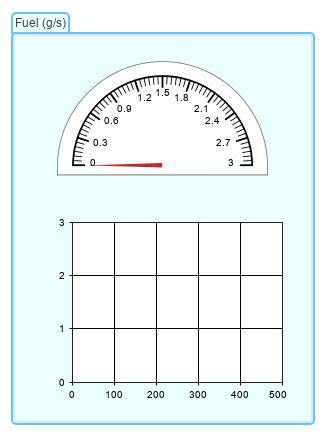
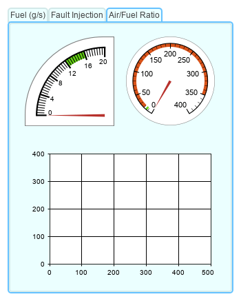
The subsystem contains four areas: Inputs, Fault
Injection, Fuel (g/s), and Air/Fuel
Ratio.
Suppose you want to use the control and display blocks in these areas to test the effect of sensor failures on the calculated air/fuel ratio and fuel consumption of a gasoline engine. Your plan consists of these steps:
Test the effect of sensor failures on the calculated air/fuel ratio.
For this task, you want a panel with two tabs:
One tab contains the control blocks from the
Fault Injectionarea that you can use to activate the sensor failures during simulation.One tab contains the display blocks from the
Air/Fuel Ratioarea that you can use to observe the effect of the failures on the air/fuel ratio.
Test the effect of sensor failures on the calculated fuel consumption.
For this task, you also want a panel with two tabs:
One tab contains the control blocks from the
Fault Injectionarea.One tab contains the display blocks from the
Fuel (g/s)area that you can use to the effect of the failures on the fuel consumption.
Pass the model to a colleague who will use your findings to make design changes to the fuel control system.
You want to hand over the model with all three panels reorganized into one panel with three tabs, and with the tabs that contain display blocks next to each other.
This example explains the process of creating the tabbed panels in your plan.
Create Panels
Start by creating one panel that contains the blocks from the Fault
Injection area and one that contains the blocks from the Fuel
(g/s) area.
If you already created a panel containing the dashboard blocks and annotations from the
Fault Injection area or the Fuel (g/s) area by
working through the examples in Getting Started with Dashboard Panels or Use Dashboard Panels to Monitor Signals and Control Parameters, skip the task for
creating that panel.
To create the Fault Injection panel, promote the dashboard blocks in
the Fault Injection area to a panel:
Draw a selection box around the blocks. Where the selection box ends, an ellipsis appears.
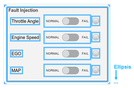
Pause on the ellipsis.
In the action bar that expands, click Promote to Panel
 . The dashboard blocks are promoted from the area to the
panel, but the annotations are not.
. The dashboard blocks are promoted from the area to the
panel, but the annotations are not.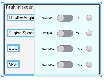
Add the annotations from the Fault Injection area to the
panel:
Select the panel.
Pause on the ellipsis that appears.
In the action bar that expands, click Edit Panel
 .
.Drag the lower left corner of the panel to the left to make room for the annotations.
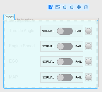
To see the annotations in the
Fault Injectionarea, drag the panel away from the area. To drag the panel, click and hold down your pointer on the panel name or on any empty spot inside the panel, then move the pointer.For each annotation from the
Fault Injectionarea, double-click the panel where you want the annotation, then type the annotation text. When you finish typing, press Enter. You can drag the annotations to move them around the panel.When you finish, click the canvas.
To rename the panel, in the Simulink® Toolstrip, on the Panels tab, in the Edit section, click Rename Panel. The Property Inspector appears. On the Parameters tab, in the Name text box, type
Fault Injection.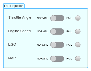
Use the same approach to create the Fuel (g/s) panel from the
dashboard blocks in the Fuel (g/s) area.
Add Empty Tab to Panel
To create the tabbed panel for the first step in your plan, add an empty tab to the
Fault Injection panel. Then, populate the tab with the blocks from the
Air/Fuel Ratio area.
To add an empty tab to a panel, select the panel. Then, in the Simulink Toolstrip, on the Panels tab, in the Edit section, click Add Tab.
To populate the new tab using the dashboard blocks from the Air/Fuel
Ratio area:
Select the new tab.
Pause on the ellipsis (…) that appears.
In the action bar that expands, click Edit Panel
.Drag the lower left corner of the panel to the left to make room for the blocks.
Drag the blocks from the
Air/Fuel Ratioarea into the new tab.When you finish, click the canvas.

Detach Tab from Panel
To create the tabbed panel for the second step in your plan, move the Fault
Injection tab to the Fuel (g/s) panel. Start by detaching the
Fault
          Injection
tab from the Air/Fuel Ratio
tab.
To detach the tab, drag the tab name away from the panel.
Attach Tab or Freestanding Panel to Another Panel
To attach the Fault Injection tab to the Fuel
(g/s) panel, dragging the Fault Injection tab by its name,
move your pointer over the Fuel (g/s) panel name. When a plus symbol
appears over the Fuel (g/s) panel name, release your pointer.
To create the tabbed panel for the third step of your plan, attach the Air/Fuel
Ratio tab to the panel with the Fault Injection tab and the
Fuel (g/s) tab.
Reorder Panel Tabs
To change the position of a tab, drag the name of the tab to a new position.
When you add a tab to a panel, the tab is always added to the right end of the tabs on that panel.
To finish the tabbed panel for the third step of your plan, reorder the panels to put
the two tabs with display blocks next to each other. The tabs with display blocks are the
Air/Fuel
          Ratio
tab and the Fuel (g/s) tab.
See Also
simulink.dashboard.switchPanelTab