Run PMSM Motor in Open Loop on Teensy Hardware
R2026bThis example shows how to use Simulink® Support Package for Arduino® Hardware to run a permanent magnet synchronous motor (PMSM) using open-loop voltage-frequency (V/F) control on a Teensy® development board.
The controller generates three-phase PWM signals that drive the motor through a BOOSTXL-DRV8305 inverter. By varying the electrical frequency while maintaining a constant voltage-to-frequency ratio, the controller changes the motor speed without requiring rotor position feedback. For more information on open-loop motor control, see Open-Loop and Closed-Loop Motor Control Techniques (Motor Control Blockset).
Prerequisites
Complete the Get Started with Arduino Hardware and Communicating with Arduino Hardware examples.
Required Hardware
To run this example, you will need the following hardware.
Teensy 4.0 hardware board
TI-Motor Bridge Driver BOOSTXL-DRV8305EVM
Teknic2310P PMSM motor
24-V DC supply
Connecting wires
Hardware Setup
Connect a 24-V DC supply source to the supply header of the DRV8305EVM driver.
Connect a PMSM motor to the motor header of the DRV8305EVM driver.
Use the connections specified in this table to connect Teensy development board and DRV8305EVM driver.

Configure Motor and Inverter Parameters
Run the arduinoTeensyPmsmPwmAdcSetup script provided with the example.
The script is pre-configured for the Teknic 2310P PMSM motor and defines the PWM timing, ADC offset, motor and inverter parameters, target hardware settings, and per-unit (PU) system parameters required by the control algorithm. If you are using a different motor, modify the motor parameters in this script to match the specifications of your motor.
Model Description
Open the arduinoMcbOpenLoopRunPmsm Simulink model.
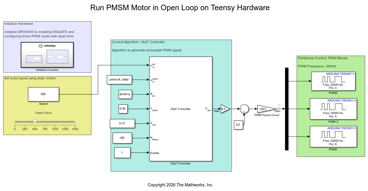
The model has four main stages:
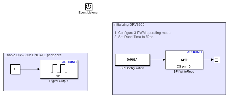
Hardware Initialization — The Initialize Function subsystem enables DRV8305EVM gate driver registers and configures SPI communication. It also configures the motor control hardware and triggers the hardware initialization sequence required for safe motor operation.
Open-Loop Control — The VbyF Controller (Motor Control Blockset) block implements open-loop V/f control for the PMSM motor. The controller regulates motor speed by varying the stator voltage and frequency. You can specify these motor parameters in the arduinoTeensyPmsmPwmAdcSetup file provided with this example. The controller uses these parameters to compute the three-phase motor voltages (Vabc) required to drive the motor.
PWM signal generation — The model generates three-phase PWM signals (PWM1, PWM2, and PWM3) for the PMSM motor voltages Vabc and controls their duty cycle.
Speed control — Use the slider to adjust the motor speed while the application runs on the hardware.
Run Simulink Model in External Mode
1. Complete the hardware connections.
2. Open arduinoMcbOpenLoopRunPmsm model.
3. Configure the model for Teensy development board. On the Modeling tab, click Model settings to open the Configuration Parameters dialog box. In the Hardware Implementation pane, set Hardware board to Teensy 4.0 or Teensy 4.1. Click OK.
4. Configure SPI mode. In the Hardware Implementation pane, expand Target hardware resources and select SPI properties. Set SPI mode to Mode 1 - Clock Polarity 0, Clock Phase 1, which is supported by the DRV8305EVM gate driver.

5. Run the model in external mode. On the Hardware tab, click Monitor & Tune.
6. Use the slider in the model to adjust the motor speed while the application runs on the hardware. You can also connect an oscilloscope to the PWM outputs and observe the generated PWM signals.
See Also
Open-Loop and Closed-Loop Motor Control Techniques (Motor Control Blockset)
Current Sensor ADC Offset and Position Sensor Calibration (Motor Control Blockset)
Measure Phase Currents of PMSM Motor in Open Loop Teensy Hardware
Estimate Angle and Speed of PMSM Motor in Open Loop on Teensy Hardware
Sensorless Field-Oriented Control of PMSM Motor Using Teensy Hardware

