jc_0531: Default transition
Guideline Publication
Control Algorithm Modeling Guidelines - Using MATLAB®, Simulink®, and Stateflow®
Sub ID Recommendations
NA-MAAB — a, b, c, d, e, f, g
JMAAB — a, b, c, d, e, f, g
MATLAB Versions
All
Rule
Sub ID a
When Decomposition of a Stateflow
Chart (Stateflow) is Exclusive (OR), the default transition shall connect
at the top of the Chart block.
When Decomposition of the state is Exclusive
(OR), the default transition shall connect immediately beneath the state.
Not Applicable
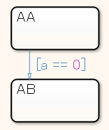
The default transition line is connected at the top.

The default transition line is not connected.
Sub ID b
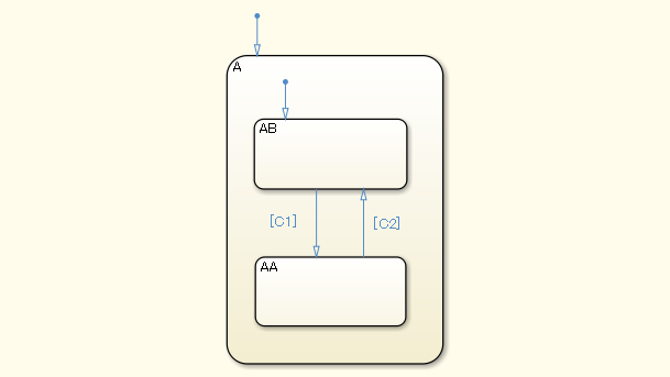
When Decomposition is set to “Parallel (AND)”, the default transition line shall not be connected.
Not Applicable
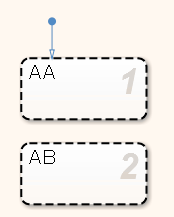
Decomposition of the parent object for states AA and AB is set to
Parallel (AND), which makes states AA and AB parallel states. The
default transition line is not connected for these parallel states.

A default transition line is connected for parallel state AA.
Sub ID c
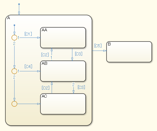
A level shall not have multiple default transitions.
Not Applicable
The level does not have multiple default transitions

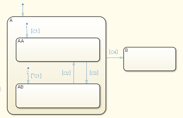
Multiple default transitions are included in the same level of state A.
Sub ID d
Default transitions shall be connected directly and positioned vertically to the upper part of the state or connective junction.
Not Applicable
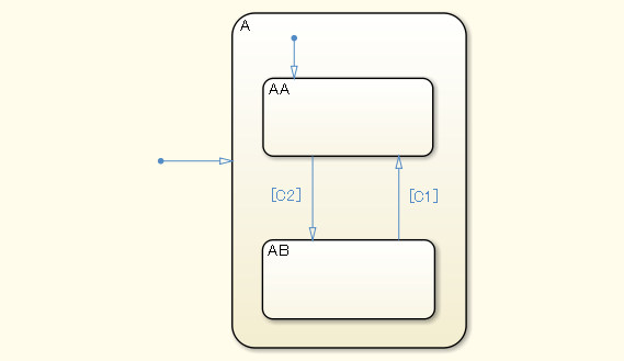
The default transition is connected vertically to the upper part of the state.

The default transition of state A is not connected vertically to the upper part of the state.
Sub ID e
The destination state or destination connective junction for the default transition shall be positioned to the top left in the same level.
Not Applicable
The default transition is positioned to the top left in the same level.
The default transition of state AB is not positioned to the top left in the same level.

Sub ID f
Default transitions shall not extend beyond the boundaries of the state.
Not Applicable
The default transition is within the boundaries of the state.

The default transition extends beyond the boundaries of the state.

Sub ID g
Configuration parameter No unconditional default
transitions shall be set to Error to
ensure that in the transition path for the default transition,
the path with the lowest priority is an unconditional transition.
Not Applicable
The path with the lowest priority in the transition path for the default transition is an unconditional transition.
The path with the lowest priority in the transition path for the default transition is not an unconditional transition.

Rationale
Sub ID a:
Simulation errors can occur when a state chart does not include default transition lines.
When default transitions are included in a flow chart, it is impossible to determine whether this is intentional or through failure to insert them.
Sub ID b:
Readability improves when there are no unnecessary default transitions.
Sub ID c:
The state may not function as intended and produce a warning when multiple default transitions are included in the same level.
Sub ID d:
Readability decreases when there are curves or variations in the angle or position of default transitions.
Sub ID e:
Readability decreases when there are variations in the position of the transition destination state or transition destination connective junction for the default transition.
Sub ID f
Readability decreases when a default transition extends beyond the boundary of a state and intersects with state boundaries and expressions.
Sub ID g:
When there is not an unconditional transition in the transition path of the default transition, the transition destination disappears if all conditions of the transition path are not met. This can result in unintended behavior.
Verification
Model Advisor check: Check default transition placement in Stateflow charts (Simulink Check)
Last Changed
R2020a
See Also
Define Exclusive and Parallel Modes by Using State Decomposition (Stateflow)
Transition Between Operating Modes (Stateflow)
How Stateflow Objects Interact During Execution (Stateflow)
Version History
Introduced in R2020a