Main Content

integralImage

Calculate 2-D integral image

Description

In an integral image, each pixel represents the cumulative sum of a corresponding input pixel with all pixels above and to the left of the input pixel.

An integral image enables you to rapidly calculate summations over image subregions. Subregion summations can be computed in constant time as a linear combination of only four pixels in the integral image, regardless of the size of the subregion. Use of integral images was popularized by the Viola-Jones algorithm [1].

J = integralImage(I) calculates the integral image from image I. The function zero-pads the top and left side of the output integral image, J.

example

J = integralImage(I,orientation) calculates the integral image with the orientation specified by orientation.

example

Examples

collapse all

Create a simple sample matrix.

I = magic(5)
I = 5×5

    17    24     1     8    15
    23     5     7    14    16
     4     6    13    20    22
    10    12    19    21     3
    11    18    25     2     9

Calculate the integral image of the sample matrix. These steps show how the first few values in the original matrix map to values in the integral image. Note that the pixel with (row, column) coordinate (r, c) in the original image corresponds to the pixel with coordinate (r+1, c+1) in the integral image.

  • The first row and column in the integral image are all 0s.

  • The pixel in the original matrix at coordinate (1, 1) with value 17 is unchanged in the integral image because there are no other pixels in the summation. Therefore, the pixel in the integral image at coordinate (2, 2) has the value 17.

  • The pixel in the original matrix at coordinate (1, 2) maps to the pixel (2, 3) in the integral image. The value is the summation of the original pixel value (24), the pixels above it (0), and the pixels to its left (17): 24 + 17 + 0 = 41.

  • The pixel in the original matrix at coordinate (1, 3) maps to the pixel (2, 4) in the integral image. The value is the summation of the original pixel value (1), the pixel above it (0), and the pixels to its left (which have already been summed to 41). Thus the value at pixel (2,4) in the integral image is 1 + 41 + 0 = 42.

J = integralImage(I)
J = 6×6

     0     0     0     0     0     0
     0    17    41    42    50    65
     0    40    69    77    99   130
     0    44    79   100   142   195
     0    54   101   141   204   260
     0    65   130   195   260   325

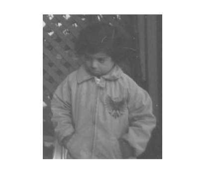
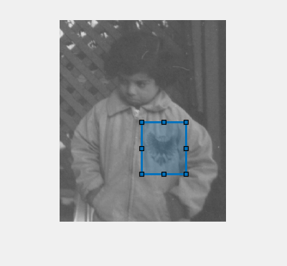
Read a grayscale image into the workspace. Display the image.

I = imread('pout.tif');
imshow(I)

Compute the integral image.

J = integralImage(I);

Use the drawrectangle tool to select a rectangular subregion. The tool returns a Rectangle object.

d = drawrectangle;

The Vertices property of the Rectangle object stores the coordinates of vertices as a 4-by-2 matrix. Vertices are ordered starting with the top-left and continuing in a clockwise direction. Split the matrix into two vectors containing the row and column coordinates. Because the integral image is zero-padded on the top and left side, increment the row and column coordinates by 1 to retrieve the corresponding elements of the integral array.

r = floor(d.Vertices(:,2)) + 1;
c = floor(d.Vertices(:,1)) + 1;

Calculate the sum of all pixels in the rectangular subregion by combining four pixels of the integral image.

regionSum = J(r(1),c(1)) - J(r(2),c(2)) + J(r(3),c(3)) - J(r(4),c(4))
regionSum = 613092

Create a simple sample matrix.

I = magic(5)
I = 5×5

    17    24     1     8    15
    23     5     7    14    16
     4     6    13    20    22
    10    12    19    21     3
    11    18    25     2     9

Create an integral image with a rotated orientation.

J = integralImage(I,'rotated')
J = 6×7

     0     0     0     0     0     0     0
     0    17    24     1     8    15     0
    17    64    47    40    38    39    15
    64    74    91   104   105    76    39
    74   105   149   188   183   130    76
   105   170   232   272   236   195   130

Define a rotated rectangular subregion. This example specifies a subregion with top corner at coordinate (1,3) in the original image. The subregion has a rotated height of 1 and width of 2.

r = 1;
c = 3;
h = 1;
w = 2;

Get the value of the four corner pixels of the subregion in the integral image.

regionBottom = J(r+w+h,c-h+w+1);
regionTop = J(r,c+1);
regionLeft = J(r+h,c-h+1);
regionRight = J(r+w,c+w+1);
regionCorners = [regionBottom regionTop regionLeft regionRight]
regionCorners = 1×4

   105     0    24    39

Calculate the sum of pixels in the subregion by summing the four corner pixel values.

regionSum = regionBottom + regionTop - regionLeft - regionRight
regionSum = 
42

Input Arguments

collapse all

Image, specified as a numeric array of any dimension. If the input image has more than two dimensions (ndims(I)>2), such as for an RGB image, then integralImage computes the integral image for all 2-D planes along the higher dimensions.

Data Types: single | double | int8 | int16 | int32 | uint8 | uint16 | uint32

Image orientation, specified as "upright" or "rotated". If you set the orientation to "rotated", then integralImage returns the integral image for computing sums over rectangles rotated by 45 degrees.

Data Types: char | string

Output Arguments

collapse all

Integral image, returned as a numeric matrix. The function zero-pads the integral image according to the orientation of the image. Such sizing facilitates the computation of pixel sums along image boundaries. The integral image, J, is essentially a padded version of the value cumsum(cumsum(I,2)).

Image OrientationSize of Integral Image
Upright integral imageZero-padded on top and left. size(J) = size(I)+1
Rotated integral imageZero-padded at the top, left, and right. size(J) = size(I)+[1 2]

Data Types: double

Algorithms

collapse all

Integral Image Summation

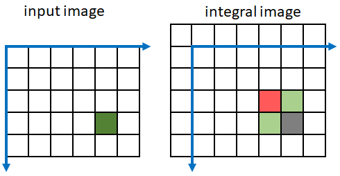
Every pixel in an integral image represents the summation of the corresponding input pixel value with all input pixels above and to the left of the input pixel. Because integralImage zero-pads the resulting integral image, a pixel with (row, column) coordinate (m, n) in the original image maps to the pixel with coordinate (m+1, n+1) in the integral image.

In the figure, the current pixel in the input image is the dark green pixel at coordinate (4, 5). All pixels in the input image above and to the left of the input pixel are colored in light green. The summation of the green pixel values is returned in the integral image pixel with coordinate (5, 6), colored in gray.

A sample input pixel on the left, and the corresponding output pixel in the integral image on the right.

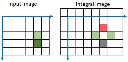
integralImage performs a faster computation of the integral image by summing pixel values in both the input image and the integral image. Pixel (m, n) in integral image J is a linear combination of only four pixels: one from the input image and three previously-calculated pixels from the integral image.

J(m,n) = J(m,n-1) + J(m-1,n) + I(m-1,n-1) - J(m-1,n-1)

This figure shows which pixels are included in the sum when calculating the integral image at the gray pixel. Green pixels add to the sum and red pixels subtract from the sum.

A sample input pixel on the left, and the three pixels in the integral image on the right, that contribute to the value of the output pixel in the integral image.

Rotated Integral Image Summation

If you specify the image orientation as "rotated", then pixels in an integral image represent the summation of a corresponding input pixel value with all input pixels that are diagonally above the input pixel. integralImage performs the summation along diagonal lines. This approach is less computationally intensive than rotating the image and calculating the integral image in rectilinear directions.

In the figure, the current pixel in the input image is the dark green pixel at coordinate (4, 5). All pixels in the input image diagonally above the input pixel are colored in light green. The summation of the green pixel values is returned in the integral image pixel with coordinate (5, 6), colored in gray.

Pixels that are diagonally above the input pixel in the input image on the left, and the corresponding output pixel in the rotated integral image on the right.

integralImage performs a faster computation of the rotated integral image by summing pixel values in both the input image and the integral image. Pixel (m, n) in integral image J is a linear combination of only five pixels: two from the input image and three previously-calculated pixels from the integral image:

J(m,n) = J(m-1,n-1) + J(m-1,n+1) - J(m-2,n) + I(m-1,n-1) + I(m-2,n-1)

This figure shows which pixels are included in the sum when calculating the integral image at the gray pixel. Green pixels add to the sum and red pixels subtract from the sum.

The two input pixels on the left, and the three pixels in the integral image on the right, that contribute to the value of the output pixel in the rotated integral image.

Image Subregion Summation

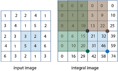
A subregion in an upright orientation with top-left coordinate (m,n), height h, and width w in the original image has the summation:

regionSum = J(m–1,n–1) + J(m+h–1,n+w–1) – J(m+h–1,n–1) – J(m-1,n+w-1)

For example, in the input image below, the summation of the blue shaded region is: 46 – 22 – 20 + 10 = 14. The calculation subtracts the regions above and to the left of the shaded region. The area of overlap is added back to compensate for the double subtraction.

Four pixels in a subregion of the input image on the left, and the regions that contribute to the summation of the subregion in the integral image on the right.

A subregion in an rotated orientation uses a different definition of height and width [2]. The summation of the region is:

regionSum = J(m+h+w,n-h+w+1) + J(m,n+1) - J(m+h,n-h+1) - J(m+w,n+w+1)

References

[1] Viola, P., and M. J. Jones. "Rapid Object Detection using a Boosted Cascade of Simple Features". Proceedings of the 2001 IEEE Computer Society Conference on Computer Vision and Pattern Recognition. 2001. Vol. 1, pp. 511–518.

[2] Lienhart, R., and J. Maydt. "An Extended Set of Haar-like Features for Rapid Object Detection". Proceedings of the 2002 IEEE International Conference on Image Processing. Sept. 2002. Vol. 1, pp. 900–903.
Extended Capabilities

Version History

Introduced in R2015b

expand all