このページは機械翻訳を使用して翻訳されました。最新版の英語を参照するには、ここをクリックします。
イーサネットAXIマネージャー
メモ
Ethernet AXI マスターは Ethernet AXI マネージャーに名前が変更され、AXI マスター IP としての UDP MATLAB® は UDP AXI マネージャー IP に名前が変更されました。ソフトウェアとドキュメントでは、「マスター」と「スレーブ」という用語がそれぞれ「マネージャー」と「従属」に置き換えられます。
ユーザー データグラム プロトコル (UDP) を使用して、イーサネット経由で AXI マネージャーを統合および構成します。Ethernet AXI マネージャーを使用するには、まず次の 2 つの知的財産 (IP) ブロックをプロジェクトに含める必要があります。イーサネット メディア アクセス コントローラ (MAC) ハブと UDP AXI マネージャ。
イーサネット MAC ハブ IP
イーサネット MAC ハブ IP は、イーサネット物理層 (PHY) を UDP AXI マネージャー IP に接続します。次の Ethernet MAC ハブ IP を使用して、さまざまなタイプのインターフェイスを介してターゲット FPGA ボードを接続します。
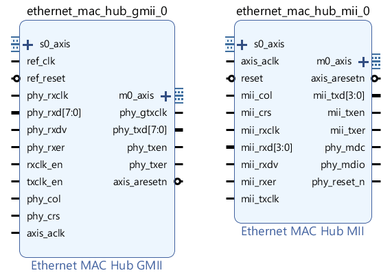
イーサネット MAC ハブ GMII IP — この IP は、ギガビット メディア独立インターフェイス (GMII) をサポートします。
イーサネット MAC ハブ MII IP — この IP は、メディア独立インターフェイス (MII) をサポートします。
イーサネット MAC ハブ GMII IP と 1G/2.5G イーサネット PCS/PMA または SGMII Xilinx® IP — これら 2 つの IP を接続して、シリアル ギガビット メディア独立インターフェイス (SGMII) をサポートします。
イーサネット MAC ハブ IP のインターフェース

次の表は、イーサネット MAC ハブ GMII とイーサネット MAC ハブ MII のポートの説明を示しています。
| ポート | 説明 |
|---|---|
| s0_axis | AXI-stream 従属インターフェース。このポートを UDP AXI マネージャー IP の m_axis ポートに接続します。 |
| m0_axis | AXI-ストリーム マネージャー インターフェイス。このポートを UDP AXI マネージャー IP の s_axis ポートに接続します。 |
イーサネット MAC ハブ GMII IP ポート
| ポート | 方向 | 説明 |
|---|---|---|
| ref_clk | Input | phy_gtxclk を駆動する基準クロック信号。ref_clk の周波数は phy_rxclk クロック周波数と同じである必要があります。 |
| ref_reset | Input | IP リセット信号。 |
| phy_rxclk | Input | PHYからクロックを受信します。 |
| phy_rxd[7:0] | Input | PHYからデータ信号を受信します。 |
| phy_rxdv | Input | PHY からデータ有効制御信号を受信します。 |
| phy_rxer | Input | PHYからエラー信号を受信します。 |
| rxclk_en | Input | 受信機クロックの有効化。 |
| txclk_en | Input | 送信機クロックの有効化。 |
| phy_col | Input | PHY からの衝突検出信号。 |
| phy_crs | Input | PHY からのキャリアセンス検出信号。 |
| axis_aclk | Input | AXI-stream インターフェイスのクロック信号。 |
| phy_gtxclk | 出力 | PHYへのクロック。 |
| phy_txd[7:0] | 出力 | データ信号をPHYに送信します。 |
| phy_txen | 出力 | 有効制御信号を PHY に送信します。 |
| phy_txer | 出力 | エラー信号をPHYに送信します。 |
| axis_aresetn | 出力 | アクティブローリセット。AXI-stream インターフェイスのリセット信号。このポートを使用して、ダウンストリーム AXI ペリフェラルをリセットできます。 |
イーサネット MAC ハブ MII IP ポート
| ポート | 方向 | 説明 |
|---|---|---|
| axis_aclk | Input | AXI-stream インターフェイスのクロック信号。 |
| リセット | Input | IP リセット信号。 |
| mii_col | Input | PHY からの衝突検出信号。 |
| mii_crs | Input | PHY からのキャリアセンス検出信号。 |
| mii_rxclk | Input | PHYからクロック信号を受信します。 |
| mii_rxd[3:0] | Input | PHYからデータ信号を受信します。 |
| mii_rxdv | Input | PHY からデータ有効制御信号を受信します。 |
| mii_rxer | Input | PHYからエラー信号を受信します。 |
| mii_txclk | Input | PHYからクロック信号を送信します。 |
| axis_aresetn | 出力 | アクティブローリセット。AXI-stream インターフェイスのリセット信号。このポートを使用して、ダウンストリーム AXI ペリフェラルをリセットできます。 |
| mii_txd[3:0] | 出力 | データ信号をPHYに送信します。 |
| mii_txen | 出力 | 有効制御信号を PHY に送信します。 |
| mii_txer | 出力 | エラー信号をPHYに送信します。 |
| phy_mdc | 出力 | PHY への管理データ クロック (MDC) 信号。 |
| phy_mdio | インアウト | 管理データ入出力 (MDIO) コントローラとの通信用のデータ信号。 |
| phy_reset_n | 出力 | PHY へのアクティブ ロー リセット信号。 |
ポート接続の詳細については、イーサネットベースの AXI マネージャーを使用して FPGA メモリにアクセスする を参照してください。
SGMII 用イーサネット MAC ハブ IP 接続
SGMII の場合、この図に示すように、イーサネット MAC ハブ GMII IP を 1G/2.5G イーサネット PCS/PMA または SGMII Xilinx IP に接続します。

イーサネット MAC ハブ IP パラメータ
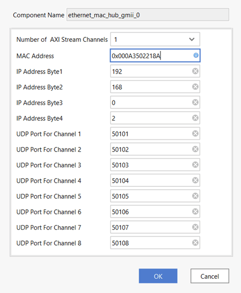
ターゲット FPGA ボードのイーサネット インターフェイスのタイプに基づいて、デザイン内でイーサネット MAC ハブ GMII またはイーサネット MAC ハブ MII HDL IP をインスタンス化します。デザインで Ethernet MAC Hub IP をインスタンス化した後、構成用のブロック パラメータを開きます。この図は、イーサネット MAC ハブ GMII IP のブロック パラメータを示しています。

次のパラメータを設定します。
Number of AXI Stream Channels — このパラメータは、イーサネット MAC ハブ IP 内の AXI ストリーム チャネルの数を決定します。この値は 1 ~ 8 の整数として選択します。既定値は
1です。IP Address Byte1, IP Address Byte2, IP Address Byte3, IP Address Byte4 — これらのパラメータは、デバイスの UDP インターネット プロトコル (IP) アドレスを構成する 0 ~ 255 の範囲の 4 バイトを設定します。このアドレスは、
aximanagerオブジェクトのDeviceAddressプロパティ値と一致する必要があります。UDP Port For Channel 1, UDP Port For Channel 2, UDP Port For Channel 3, UDP Port For Channel 4, UDP Port For Channel 5, UDP Port For Channel 6, UDP Port For Channel 7, UDP Port For Channel 8 — これらのパラメータは UDP ポート番号を設定します。各パラメータ値を 255 ~ 65,535 の整数として指定します。これらのポート番号は、
aximanagerオブジェクトのPortプロパティ値と一致する必要があります。
イーサネット MAC ハブの IP 制限
SGMII の場合、AXI-Stream インターフェイス (axis_aclk) のクロック信号は 50 MHz に制限されます。
イーサネット管理インターフェイス MDC および MDIO では、イーサネット PHY を構成することはできません。
UDP AXI マネージャー IP
UDP AXI Manager HDL IP は、イーサネット MAC ハブ IP をアプリケーション IP に接続します。UDP AXI マネージャー IP は、AXI ペリフェラルと MATLAB の間でデータを変換するブリッジとして機能します。
UDP AXI マネージャー IP のインターフェース

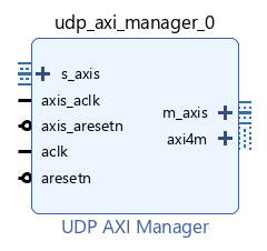
UDP AXI Manager IP のインターフェースには、これらの表に記載されているポートが含まれます。
| ポート | 説明 |
|---|---|
| s_axis | AXI-stream 従属インターフェース。 |
| m_axis | AXI-ストリーム マネージャー インターフェイス。 |
| axi4m | AXI4 フル マネージャー インターフェイス。 |
UDP AXI マネージャー IP ポート
| ポート | 方向 | 説明 |
|---|---|---|
| axis_aclk | Input | AXI-stream インターフェイスのクロック信号。 |
| axis_aresetn | Input | AXI-stream インターフェイスのアクティブ ロー リセット信号。 |
| aclk | Input | AXI4 フル インターフェイスのクロック信号。 |
| aresetn | Input | アクティブローリセット。AXI4 フル インターフェースのリセット信号。 |
UDP AXI マネージャー IP パラメーター
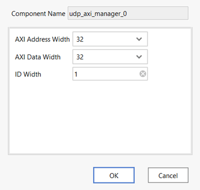
デザインで UDP AXI Manager IP をインスタンス化した後、構成用のブロック パラメータを開きます。

次のパラメータを設定します。
AXI Address Width — このパラメータはビット単位のアドレスバス幅です。IP は 32 ビットまたは 64 ビットをサポートします。
AXI Data Width — このパラメータはビット単位のデータバス幅です。IP は 32 ビットまたは 64 ビットをサポートします。
ID Width — このパラメータはビット単位の ID 幅です。その値は、AXI4 下位の ID 幅と一致する必要があります。
プログラムが FPGA ボード上で実行されている場合、aximanager オブジェクトを使用して AXI マネージャー オブジェクトを作成できます。ボード上の下位メモリ位置にアクセスするには、readmemory および writememory オブジェクト関数を使用します。