CORDIC Atan2 Verilog コードからの Simulink モデルの生成
この例では、関数 importhdl を使用して Verilog® コードを含むファイルをインポートし、対応する Simulink® モデルを生成する方法を示します。importhdl は、指定された Verilog ファイルをインポートして解析し、対応する Simulink モデルを生成します。この例の Verilog コードには CORDIC atan2 アルゴリズムが含まれています。
CORDIC 2 引数逆正接 (atan2) の Verilog 設計
次の Verilog 入力ファイルは CORDIC atan2 アルゴリズムを実装します。
cordic_atan2_verilog_file = 'cordic_atan2.v';
type(cordic_atan2_verilog_file);
`timescale 1ns / 1ps

module cordic_atan2(
    input clk,                      // clock
    input reset,                    // reset to the system
    input enable,                   // enable
    input signed [15:0] x_in,       // Input x value
    input signed [15:0] y_in,       // Input Y value
    output reg signed [15:0] theta  // Input theta value
);

// Pipeline the input values
reg signed [17:0]x_in_d; reg signed [17:0]y_in_d;
always @(posedge clk)
begin
    if(reset)    begin
        x_in_d <={18{1'b0}};
        y_in_d <={18{1'b0}};
    end else if(enable) begin
        // extend the input values for intermediate calculations
        x_in_d <= {{2{x_in[15]}},x_in};
        y_in_d <= {{2{y_in[15]}},y_in};
    end
end
// pre quad correction logic
reg x_qaud_adjust;  reg y_qaud_adjust;
reg y_non_zero;  reg signed [17:0]x_pre_quad_out;
reg signed [17:0]y_pre_quad_out;

always @(posedge clk)begin
    if(reset)begin
        x_pre_quad_out <= {18{1'b0}};
        y_pre_quad_out <= {18{1'b0}};
        x_qaud_adjust  <= 1'b0;
        y_qaud_adjust  <= 1'b0;
        y_non_zero     <=1'b0;
    end
    else if(enable)begin
        if(x_in_d[17] == 1'b1)begin
            x_pre_quad_out <= -x_in_d;
            x_qaud_adjust  <= 1'b1;
        end
        else begin
            x_pre_quad_out <= x_in_d;
            x_qaud_adjust  <= 1'b0;
        end
        if(y_in_d[17] == 1'b1)begin
            y_pre_quad_out <= -y_in_d;
            y_qaud_adjust  <= 1'b1;
            y_non_zero     <=1'b1;
        end
        else begin
            y_pre_quad_out <= y_in_d;
            y_qaud_adjust  <= 1'b0;
            y_non_zero     <= |y_in_d; // reduction or for test non zero or not
        end
    end
end

//LOOKUP TABLE FOR THE ANGLES
wire signed [15:0]LUT[0:14];
wire signed [17:0]x_k[0:15];
wire signed [17:0]y_k[0:15];
wire signed [17:0]z_k[0:15];
wire signed [15:0]theta_temp;
parameter PI = 16'sh6488;

assign LUT[0]  = 16'h1922;
assign LUT[1]  = 16'h0Ed6;
assign LUT[2]  = 16'h07D7;
assign LUT[3]  = 16'h03FB;
assign LUT[4]  = 16'h01FF;
assign LUT[5]  = 16'h0100;
assign LUT[6]  = 16'h0080;
assign LUT[7]  = 16'h0040;
assign LUT[8]  = 16'h0020;
assign LUT[9]  = 16'h0010;
assign LUT[10] = 16'h0008;
assign LUT[11] = 16'h0004;
assign LUT[12] = 16'h0002;
assign LUT[13] = 16'h0001;
assign LUT[14] = 16'h0000;

assign x_k[0]  = x_pre_quad_out;
assign y_k[0]  = y_pre_quad_out;

wire  signed [17:0]theta_temp0;
assign theta_temp0 = z_k[15];
assign theta_temp  = theta_temp0[15:0];
assign z_k[0] = 18'd0;

//cordic iterator
genvar  i;
generate
for (i = 0; i<15; i =i+1)
begin
    Kernel cordic_iterator (.clk (clk),
        .reset(reset),
        .enable  (enable ),
        .itr_num(i),
        .x_in(x_k[i]),
        .y_in(y_k[i]),
        .z_in(z_k[i]),
        .lut_constant(LUT[i]),
        .x_out(x_k[i+1]),
        .y_out(y_k[i+1]),
        .z_out(z_k[i+1])
    );
end
endgenerate

// matching delays for the control signls of the pre quadrant correction logic
reg x_qaud_adjust_match_delay[0:14];
reg y_qaud_adjust_match_delay[0:14];
reg y_non_zero_match_delay[0:14];
integer k;
always @(posedge clk)begin
    if(reset)begin
        x_qaud_adjust_match_delay[0] <= 1'b0; y_qaud_adjust_match_delay[0] <= 1'b0;
        y_non_zero_match_delay   [0] <= 1'b0; x_qaud_adjust_match_delay[1] <= 1'b0;
        y_qaud_adjust_match_delay[1] <= 1'b0; y_non_zero_match_delay   [1] <= 1'b0;
        x_qaud_adjust_match_delay[2] <= 1'b0; y_qaud_adjust_match_delay[2] <= 1'b0;
        y_non_zero_match_delay   [2] <= 1'b0; x_qaud_adjust_match_delay[3] <= 1'b0;
        y_qaud_adjust_match_delay[3] <= 1'b0; y_non_zero_match_delay   [3] <= 1'b0;
        x_qaud_adjust_match_delay[4] <= 1'b0; y_qaud_adjust_match_delay[4] <= 1'b0;
        y_non_zero_match_delay   [4] <= 1'b0; x_qaud_adjust_match_delay[5] <= 1'b0;
        y_qaud_adjust_match_delay[5] <= 1'b0; y_non_zero_match_delay   [5] <= 1'b0;
        x_qaud_adjust_match_delay[6] <= 1'b0; y_qaud_adjust_match_delay[6] <= 1'b0;
        y_non_zero_match_delay   [6] <= 1'b0; x_qaud_adjust_match_delay[7] <= 1'b0;
        y_qaud_adjust_match_delay[7] <= 1'b0; y_non_zero_match_delay   [7] <= 1'b0;
        x_qaud_adjust_match_delay[8] <= 1'b0; y_qaud_adjust_match_delay[8] <= 1'b0;
        y_non_zero_match_delay   [8] <= 1'b0; x_qaud_adjust_match_delay[9] <= 1'b0;
        y_qaud_adjust_match_delay[9] <= 1'b0; y_non_zero_match_delay   [9] <= 1'b0;
        x_qaud_adjust_match_delay[10] <= 1'b0; y_qaud_adjust_match_delay[10] <= 1'b0;
        y_non_zero_match_delay   [10] <= 1'b0; x_qaud_adjust_match_delay[11] <= 1'b0;
        y_qaud_adjust_match_delay[11] <= 1'b0; y_non_zero_match_delay   [11] <= 1'b0;
        x_qaud_adjust_match_delay[12] <= 1'b0; y_qaud_adjust_match_delay[12] <= 1'b0;
        y_non_zero_match_delay   [12] <= 1'b0; x_qaud_adjust_match_delay[13] <= 1'b0;
        y_qaud_adjust_match_delay[13] <= 1'b0; y_non_zero_match_delay   [13] <= 1'b0;
        x_qaud_adjust_match_delay[14] <= 1'b0; y_qaud_adjust_match_delay[14] <= 1'b0;
        y_non_zero_match_delay   [14] <= 1'b0;
    end
    else if(enable) begin
        x_qaud_adjust_match_delay[0] <=x_qaud_adjust;
        y_qaud_adjust_match_delay[0] <=y_qaud_adjust;
        y_non_zero_match_delay[0]    <=y_non_zero;
        for(k =0; k <14 ;k = k+1)begin
            x_qaud_adjust_match_delay[k+1] <=  x_qaud_adjust_match_delay[k];
            y_qaud_adjust_match_delay[k+1] <= y_qaud_adjust_match_delay[k];
            y_non_zero_match_delay[k+1] <= y_non_zero_match_delay[k];
        end
    end
end
// post quadrant correction logic

always @(posedge clk) begin
    if(reset)
        theta<=16'd0;
    else if(enable)begin
        if(y_non_zero_match_delay[14])begin
            if(x_qaud_adjust_match_delay[14])begin
                if(y_qaud_adjust_match_delay[14])
                    theta <=theta_temp -PI;
                else
                    theta <=PI -theta_temp;
            end
            else begin
                if(y_qaud_adjust_match_delay[14])
                    theta <= -theta_temp;
                else
                    theta <= theta_temp;
            end
        end
        else if(x_qaud_adjust_match_delay[14])begin
            theta <= PI;
        end
        else begin
            theta <= 16'd0;
        end
    end
end

endmodule

module  Kernel(
    input clk,
    input reset,
    input enable,
    input signed [17:0]x_in,
    input signed [17:0]y_in,
    input signed [17:0]z_in,
    input [4:0]itr_num,
    input signed [15:0]lut_constant,
    output reg signed [17:0]x_out,
    output reg signed [17:0]y_out,
    output reg signed [17:0]z_out);

wire signed [17:0] lut_constant_signExtension = {{2{lut_constant[15]}},lut_constant};

always @(posedge clk)begin
    if(reset)begin
        x_out <={18{1'b0}};
        y_out <={18{1'b0}};
        z_out <= {18{1'b0}};
    end
    else if(enable)begin
        if(y_in[17])begin
            x_out <= x_in -(y_in>>>itr_num);
            y_out <= y_in + (x_in>>>itr_num);
            z_out <= z_in  - lut_constant_signExtension;
        end
        else begin
            x_out <= x_in +(y_in>>>itr_num);
            y_out <= y_in - (x_in>>>itr_num);
            z_out <= z_in  + lut_constant_signExtension;
        end
    end
end

endmodule
この Verilog 設計には、次のようなよく使用される各種 Verilog 構造が含まれています。
連続代入
always ブロック
条件付きステートメント
モジュールのインスタンス化
generate 文
For ループ
CORDIC atan2 アルゴリズムを含む HDL ファイルのインポート
Verilog ファイルをインポートするには、ファイル名を関数 importhdl への引数として指定します。
importhdl(cordic_atan2_verilog_file);
### Parsing <a href="matlab:edit('cordic_atan2.v')">cordic_atan2.v</a>.
### Top Module name: 'cordic_atan2'.
### Identified ClkName::clk.
### Identified RstName::reset.
### Identified ClkEnbName::enable.
Warning: Unused signals detected in the Demux block created for vector index signal 'x_k'. A Demux block created for a vector index signal has all possible output signals based on the size and dimensions provided.
Warning: Unused signals detected in the Demux block created for vector index signal 'y_k'. A Demux block created for a vector index signal has all possible output signals based on the size and dimensions provided.
### Hdl Import parsing done.
### Removing unconnected components.
### Unconnected components detected when importing the HDL code. These components are removed from the generated Simulink model.
### Creating Target model cordic_atan2
### Begin model generation 'cordic_atan2'...
### Rendering DUT with optimization related changes (IO, Area, Pipelining)...
### Start Layout...
### Working on hierarchy at ---> 'cordic_atan2'.
### Laying out components.
### Working on hierarchy at ---> 'cordic_atan2/cordic_atan2'.
### Laying out components.
### Working on hierarchy at ---> 'cordic_atan2/cordic_atan2/cordic_iterator'.
### Laying out components.
### Drawing block edges...
### Working on hierarchy at ---> 'cordic_atan2/cordic_atan2/cordic_iterator1'.
### Laying out components.
### Drawing block edges...
### Working on hierarchy at ---> 'cordic_atan2/cordic_atan2/cordic_iterator10'.
### Laying out components.
### Drawing block edges...
### Working on hierarchy at ---> 'cordic_atan2/cordic_atan2/cordic_iterator11'.
### Laying out components.
### Drawing block edges...
### Working on hierarchy at ---> 'cordic_atan2/cordic_atan2/cordic_iterator12'.
### Laying out components.
### Drawing block edges...
### Working on hierarchy at ---> 'cordic_atan2/cordic_atan2/cordic_iterator13'.
### Laying out components.
### Drawing block edges...
### Working on hierarchy at ---> 'cordic_atan2/cordic_atan2/cordic_iterator14'.
### Laying out components.
### Drawing block edges...
### Working on hierarchy at ---> 'cordic_atan2/cordic_atan2/cordic_iterator2'.
### Laying out components.
### Drawing block edges...
### Working on hierarchy at ---> 'cordic_atan2/cordic_atan2/cordic_iterator3'.
### Laying out components.
### Drawing block edges...
### Working on hierarchy at ---> 'cordic_atan2/cordic_atan2/cordic_iterator4'.
### Laying out components.
### Drawing block edges...
### Working on hierarchy at ---> 'cordic_atan2/cordic_atan2/cordic_iterator5'.
### Laying out components.
### Drawing block edges...
### Working on hierarchy at ---> 'cordic_atan2/cordic_atan2/cordic_iterator6'.
### Laying out components.
### Drawing block edges...
### Working on hierarchy at ---> 'cordic_atan2/cordic_atan2/cordic_iterator7'.
### Laying out components.
### Drawing block edges...
### Working on hierarchy at ---> 'cordic_atan2/cordic_atan2/cordic_iterator8'.
### Laying out components.
### Drawing block edges...
### Working on hierarchy at ---> 'cordic_atan2/cordic_atan2/cordic_iterator9'.
### Laying out components.
### Drawing block edges...
### Drawing block edges...
### Drawing block edges...
### Model generation complete.
### Setting model parameters.
### Generated model file /tmp/Bdoc26a_3146167_3710757/tp4873507c/hdlcoder-ex38650911/hdlimport/cordic_atan2/cordic_atan2.slx.
### Importhdl completed.
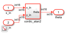
importhdl は、入力ファイルを解析し、MATLAB™ コマンド ウィンドウにインポート処理のメッセージを表示します。インポートすると、生成された Simulink モデル cordic_atan2.slx へのリンクが示されます。生成されたモデルは、入力 Verilog ファイル内の最上位モジュールと同じ名前を使用します。
生成された Simulink モデルの確認
生成された Simulink モデルを開くには、コマンド ウィンドウのリンクをクリックします。このモデルは、現在のフォルダーに対して相対的なパス hdlimport/cordic_atan2 に保存されます。モデルをシミュレートしてシミュレーション結果を確認できます。
open_system('hdlimport/cordic_atan2/cordic_atan2')
Simulink.BlockDiagram.arrangeSystem('cordic_atan2')
set_param('cordic_atan2', 'UnconnectedOutputMsg', 'None');
sim('hdlimport/cordic_atan2/cordic_atan2.slx');
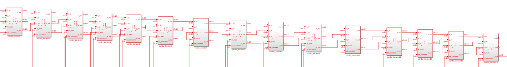
生成されたモジュール インスタンス
Verilog コードは、generate 文を使用して 15 個のカーネル モジュールをインスタンス化します。生成された Simulink モデルに 15 個のカーネル モジュールが表示されます。
generate
    for (i = 0; i<15; i =i+1)
    begin
        Kernel cordic_iterator (.clk(clk),
                                .reset(reset),
                                .enable(enable),
                                .itr_num(i),
                                .x_in(x_k[i]),
                                .y_in(y_k[i]),
                                .z_in(z_k[i]),
                                .lut_constant(LUT[i]),
                                .x_out(x_k[i+1]),
                                .y_out(y_k[i+1]),
                                .z_out(z_k[i+1]));
    end
endgenerate
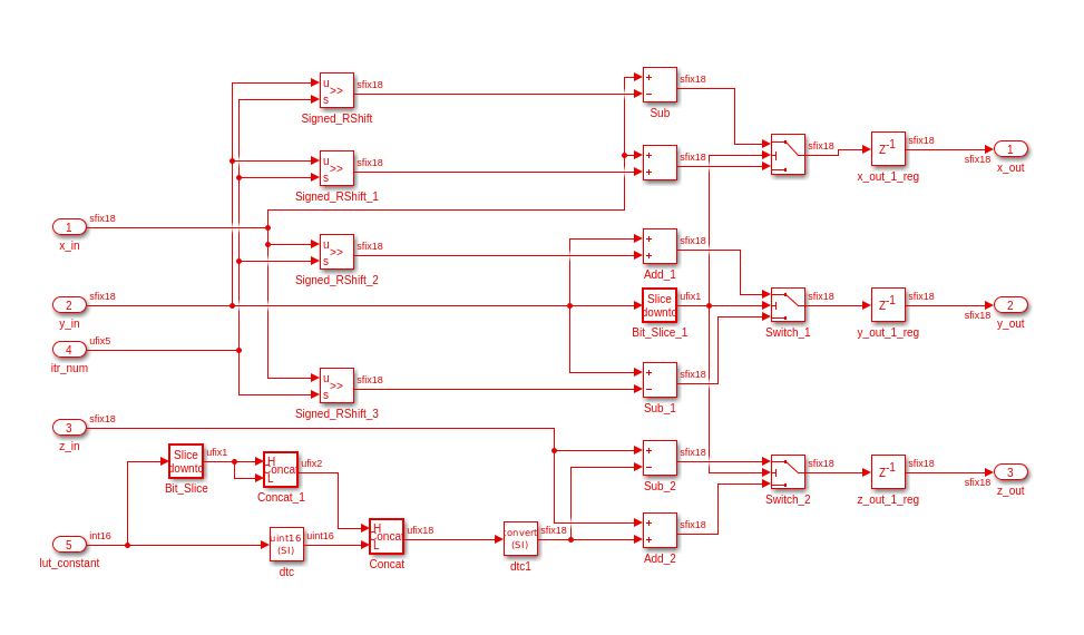
カーネル モジュールの Simulink モデル
module  Kernel(
    input clk,
    input reset,
    input enable,
    input signed [17:0]x_in,
    input signed [17:0]y_in,
    input signed [17:0]z_in,
    input [4:0]itr_num,
    input signed [15:0]lut_constant,
    output reg signed [17:0]x_out,
    output reg signed [17:0]y_out,
    output reg signed [17:0]z_out);
wire signed [17:0] lut_constant_signExtension = {{2{lut_constant[15]}},lut_constant};
always @(posedge clk)begin
      if(reset)begin
         x_out <={18{1'b0}};
         y_out <={18{1'b0}};
         z_out <= {18{1'b0}};
      end
    else if(enable)begin
        if(y_in[17])begin
            x_out <= x_in -(y_in>>>itr_num);
            y_out <= y_in + (x_in>>>itr_num);
            z_out <= z_in  - lut_constant_signExtension;
        end
        else begin
            x_out <= x_in +(y_in>>>itr_num);
            y_out <= y_in - (x_in>>>itr_num);
            z_out <= z_in  + lut_constant_signExtension;
          end
      end
 end
endmodule