Getting Started with PPU Accelerator for Infineon AURIX TC4x Microcontrollers
This example shows how to use the parallel processing unit (PPU) of Infineon AURIX TC4x Microcontrollers to generate optimized code. It also shows how to configure the custom storage class and memory sections to control the placement of code and data in the memory of PPU. PPU is a specialized hardware accelerator that you can use to speed up the highly parallel vector computations.
This example includes a top-level model and two reference models that demonstrate two-way interprocess communication between the TriCore 0 processing unit and the PPU. You can deploy the generated code on an Infineon AURIX hardware board and observe the blinking of the configured LEDs on each participating processing unit to verify successful communication.
Required Hardware
Infineon AURIX TC49xN
Micro-USB cable
Power Adapter
Configure Top-Level Model
Open the top-level model, tc4x_Ipc_PPU_TC0_topModel.
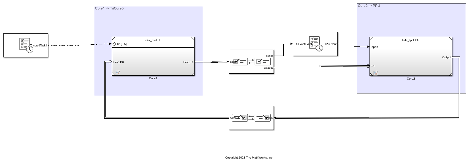
The model consists of two Interprocess Data Channel blocks that connect the two reference models. These blocks simulate communication between the two participating processing units: TriCore 0 and PPU.
The TriCore 0 reference model (tc4x_IpcTC0) runs at a base rate of 0.5 seconds with a sub-rate of 1 second. The PPU reference model (tc4x_IpcPPU) runs at a base rate of 250 milliseconds and it is triggered by an event generated by Interprocess Data Channel block.
Configure the model by following these steps:
1. In the Simulink editor, click Ctrl+E or go to Modeling > Model Settings to open the Configuration Parameters dialog box.
2. Set Hardware board to Infineon AURIX TC4x, Device Series to TC49XN, and Processing Unit to None.
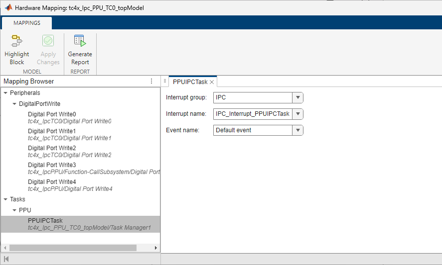
3. To configure the interrupt of PPU reference model, on the Simulink toolstrip, on the Hardware tab, click Hardware Mapping.
4. This example model uses these five LEDs on the Infineon AURIX hardware board to verify data communication between the participating cores. You can configure these pins in the Hardware Mapping tool.

This configuration ensures implementation of this data flow using LEDs when the model is deployed on the hardware board.
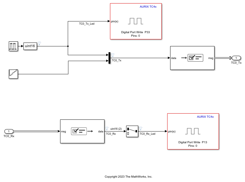
a. LED at port 33-Pin 0 blinks when TriCore 0 processing unit sends data to PPU through the Interprocess Data Channel block. TriCore 0 processing unit writes the data at every 500 milliseconds by using the Interprocess Data Write block in the TriCore 0 reference model.
b. LED at Port 33-Pin 4 blinks with an offset of 1 sample when PPU sends data to TriCore 0 processing unit through the Interprocess Data Channel1 block.
c. LED at Port 33-Pin 5 blinks at a constant rate of 1 second.
d. LED at Port 33-Pin 1 blinks when PPU receives data from TriCore 0 processing unit using the Interprocess Data Read block in the PPU reference model. This LED blinks at the same rate as the LED at Port 33-Pin 0 because PPU receives data through the event port of the Interprocess Data Channel block.
e. LED at Port 13-Pin 0 blinks at a constant rate of 1 second.
You can view these signals on the One Eye tool by loading the OneEye configuration file shipped with this example.
Configure TriCore 0 Reference Model
1. Open the TriCore0 referenced model (tc4x_IpcTC0).
2. In the Simulink editor, click Ctrl+E or go to Modeling > Model Settings to open the Configuration Parameters dialog box.
3. In the Hardware Implementation pane, set Hardware board to Infineon AURIX TC4x, Device Series to TC49XN, and Processing Unit to TriCore0.
Configure PPU Reference Model
1. Open the PPU referenced model (tc4x_IpcPPU).
2. In the Simulink editor, click Ctrl+E or go to Modeling > Model Settings to open the Configuration Parameters dialog box.
3. In the Hardware Implementation pane, set Hardware board to Infineon AURIX TC4x, Device Series to TC49XN, and Processing Unit to PPU.
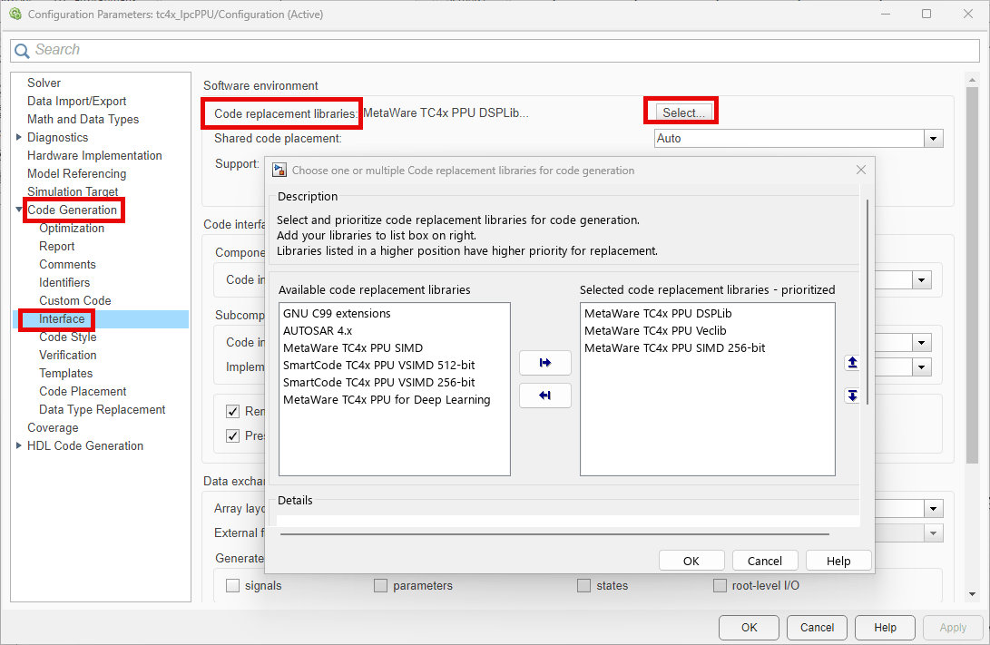
4. Expand Code Generation and select Interface. Under Software environment, click Select to view and sepcify the code replacement libraries (CRL). For more information on these libraries, see Parallel Processing Unit for Optimized Code Generation.
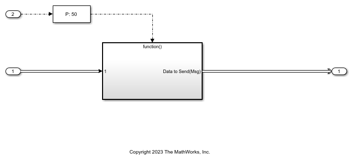
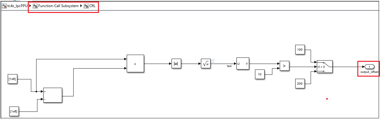
5. Open the CRL subsystem in the model. The output_offset signal determines the offset added to the data received from TriCore 0 reference model and the result is then sent back to TriCore 0 reference model.
This subsystem demonstrates CRL functionality for optimized code generation.
Custom Storage Class for PPU
The pre-configured PPU reference model uses custom storage class and memory sections to control the placement of code and model data elements in the PPU memory.
Load aurixppumemorydemospkg in model
1. Open the PPU reference model (tc4x_IpcPPU).
2. To enable the embedded coder features, in the Simulink tool strip, on the Apps tab, select Embedded Coder. This action adds a C Code tab to the toolstrip.
3. In the C Code tab, select Code Interface > Embedded Coder Dictionary.
4. The Embedded Coder Dictionary window displays the code interface configuration stored in the dictionary. In the left pane of the dictionary window, select Memory and click Manage Packages.
5. In the Manage Packages window, click Refresh and Set Select package to aurixppumemorydemospkg. To load the package in the model, click Load.

6. With the PPU custom storage class aurixppumemorydemospkg, you can use these storage classes for code mapping.
PPUUncachedLMUBssStorageClass– Maps an uninitialized signal to the Bss section of the LMU which is accessible through the Linker file of PPU.
PPUUncachedLMUDataStorageClass– Maps a non-zero initialized signal to the data section of the LMU which is accessible through the linker file of PPU.
PPUUNcachedCSMStorageClass– Maps a signal to the uncached CSM section defined in the linker file of PPU.
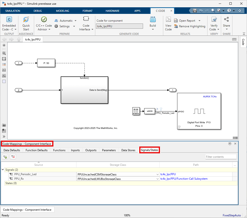
Configure Custom Storage Class
Use code mappings editor to map the memory sections and storage classes for functions, signals, code, and data elements in the model. For more information, see Code Mappings Editor — C.
Generate Code and Deploy Model on Target Hardware
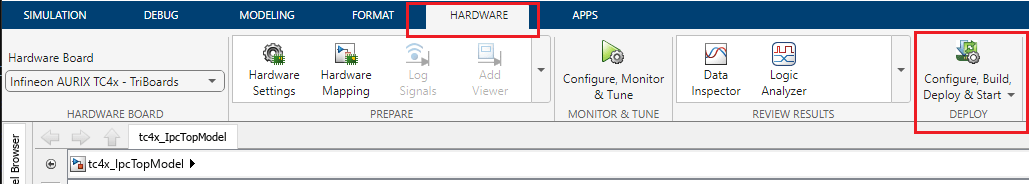
1. Click Configure, Build, Deploy & Start on the Hardware tab to launch the SoC Builder tool.
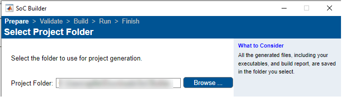
2. In the SoC Builder, prepare the model by first specifying the folder to use for project generation. Click Next.
3. In the Review Hardware Mapping section, click View/Edit to confirm the Hardware Mapping. Click Next.
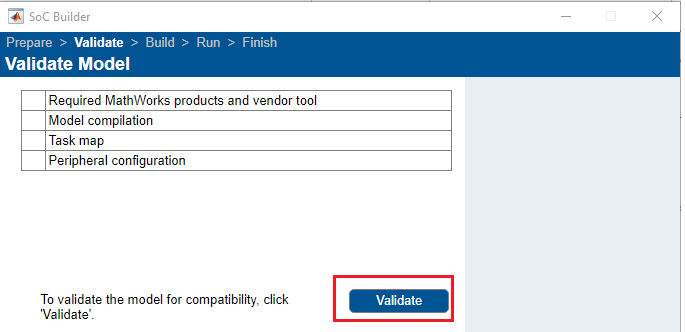
4. In the Validate Model section, click Validate to check the model against the selected board (Infineon AURIX TC4x).
Note: The presence of PPU core in the model results in model compilation error during this validation step in SoC builder tool. To resolve the issue, run the following command in the MATLAB® command prompt:
Simulink.fileGenControl('set','CodeGenFolderStructure',Simulink.filegen.CodeGenFolderStructure.TargetEnvironmentSubfolder);
If the message - Model validation successfully finished - appears, click Next.
5. In the next section of SOC Builder, Build Model, click Build. This process generates the binary executable. Click Next after the build is successful.
6. Connect the Infineon AURIX Tc4x board to the host computer.
7. In the Soc Builder screen, click Load and Run. This action loads the generated binary to the connected board, programs the processor, and runs the application. Click Finish to close the Soc Builder.
8. You can observe the code generation report that contains code to model traceability or vice versa.
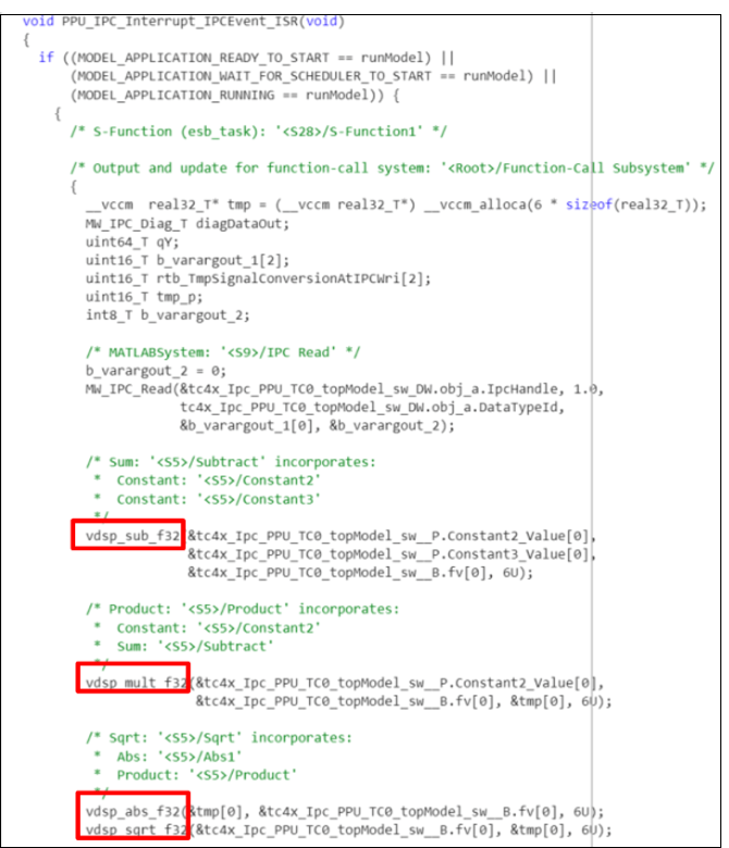
The code generation for the PPU reference model looks like this with the CRL applied.
9. To verify memory placement for model data and code, go to generated code folder and locate a MAP file named tc4x_Ipc_PPU_TC0_topModel.map.
10. Download and install the One Eye tool from Infineon to monitor signals from the hardware. Before using the One Eye tool, ensure that you download and install the latest version of the TAS/DAS tool.
11. Open the One Eye tool. Load the One Eye configuration file tc4x_IpcTopModel. OneEye file shipped with this example by clicking File > Load Configuration.
12. Load the generated tc4x_IpcTopModel_sw_TriCore0.elf file by clicking Load ELF file in Debug box viewer. Reset the hardware and check the TAS/DAS connection status to monitor the signals.

See Also
Getting Started with Multicore Modeling and Targeting for Infineon AURIX TC4x Microcontrollers
Custom Storage Class for Infineon AURIX TC4x Microcontrollers
SoC-Based Multicore Modeling Workflow for Infineon AURIX Microcontrollers
Choose Storage Class for Controlling Data Representation in Generated Code
Create Storage Classes by Using the Custom Storage Class Designer