Generate and Deploy SIMD Optimized Code for Interpolated FIR Filter on Intel Desktops
This example shows how to generate and deploy optimized code for an interpolated finite impulse response (IFIR) filter within an Intel(R) desktop environment using Simulink(R).
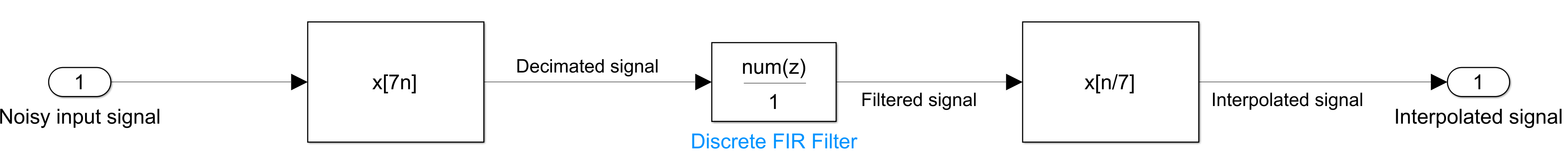
IFIR consists of FIR Decimation, Discrete FIR Filter (Simulink), and FIR Interpolation blocks. The FIR Decimation block downconverts the input signal to a lower sampling rate. The FIR Filter block filters the signal, and the FIR Interpolation block restores the sampling rate of the filtered output to the original sampling rate of the input signal.
Note: This workflow requires an Embedded Coder(R) license.
Generate optimized code using the AVX2 instruction set extensions supported by your Intel processor. These instruction set extensions have single instruction multiple data (SIMD) commands that allow you to process multiple data points simultaneously, substantially decreasing execution time and improving the performance of the generated code. Select one of these instruction set extensions based on the vector extension your processor supports. For more information, see Intel Instruction Set Extensions. This example supports the following extensions:
AVX2
FMA
SSE2
AVX512F
Alternatively, you can also use the Intel AVX2 code replacement library to generate optimized code. For more information on this workflow, see Use Intel AVX2 Code Replacement Library to Generate SIMD Code from Simulink Blocks.
This example uses the SIL/PIL Manager (Embedded Coder) application to conduct software-in-the-loop (SIL) simulations that collect the execution time metrics of the generated code. Compare the execution time of the generated SIMD code with plain C code. The generated SIMD code executes much faster compared to the plain C code.
The model used in this example runs on Microsoft(R) Windows(R) and Linux environments only.
Design Interpolated FIR (IFIR) for Lowpass Response
The first step is to design the IFIR filter blocks in the model.
To open the model included with this example, execute the following command.
mdl = 'ifir_example';
open_system(mdl);
Use the ifir function to get the FIR Decimation g(z), FIR filter h(z), and FIR interpolation g(z) coefficients for the specified lowpass response parameters. The ifir function designs a periodic filter h(z), which provides the coefficients for the Discrete FIR Filter block. It also designs an image-suppressor filter g(z), which provides the coefficients for the FIR Decimation and FIR Interpolation blocks in the model.
Set the passband ripple to 0.005 dB, stopband attenuation to 80 dB, interpolation factor to 7, passband edge frequency to 0.1 π rad/sample, and stopband edge frequency to 0.101 π rad/sample.
Apass = 0.005; % dB
Astop = 80; % dB
Fstop = .101;
M = 7;
F = [.1 Fstop];
Use convertmagunits to convert the passband ripple and stop band attenuation from dB to the linear scale. Use the linear values of passband ripple and stopband attenuation in a 1-by-2 vector to design the h(z) and g(z) filters, thereby deriving the filter coefficients.
A = [convertmagunits(Apass,'db','linear','pass') convertmagunits(Astop,'db','linear','stop')];
[h,g] = ifir(M,'low',F,A);
The code to compute h(z) and g(z) is provided in the PreLoadFcn callback of the model as the FIR decimation, FIR Interpolation, and FIR Filter blocks use these coefficients as parameters. To open PreLoadFcn callback, follow these steps:
In the Simulink Toolstrip, on the Modeling tab, in the Design gallery, click Property Inspector.
With no selection at the top level of the model, on the Properties tab, in the Callbacks section, select
PreLoadFcn.
To distinguish the performance metrics of the IFIR filter in the execution profile report, create an atomic subsystem consisting of the FIR decimation, FIR Interpolation, and FIR Filter blocks. To create a subsystem, select the block, right-click it, then click on the option Create Subsystem from Selection. To make the subsystem atomic, select the subsystem block, go to the Subsystem Block tab and click Atomic Subsystem.
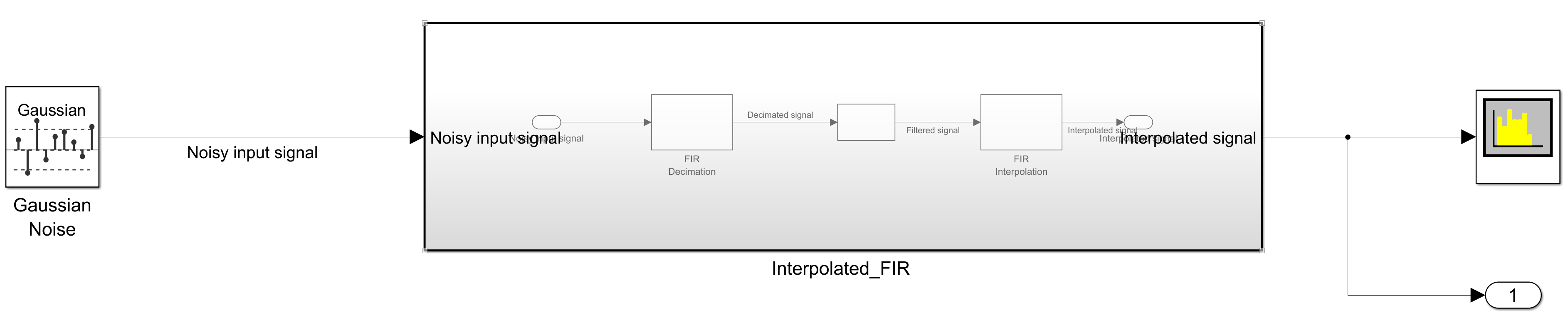
Simulate IFIR model
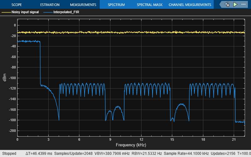
Simulate the IFIR model by running these commands. Set the default simulation time to 100 s. View the noisy input signal and the interpolated FIR filter output in the spectrum analyzer.
set_param(mdl,'SimulationMode', 'normal');
sim(mdl);
Configure IFIR Simulink Model to Generate Optimized Code
You can configure the model interactively using Configuration Parameters dialog box from the Simulink model toolstrip, or programmatically using the MATLAB command line interface.
Configure Model Using UI
To configure a Simulink model to generate SIMD code using the Intel AVX2 instruction set extensions, complete these steps
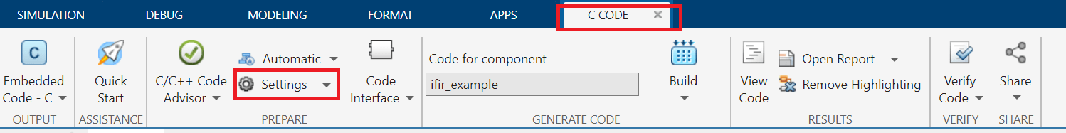
In the Apps tab of the Simulink model toolstrip, click the Embedded Coder app. In the C Code tab that opens, click Settings.
In the Hardware Implementation pane, set the Device vendor parameter to
Intel. Set the Device type parameter tox86-64(Windows 64) orx86-64(Linux 64)based on your desktop environment.
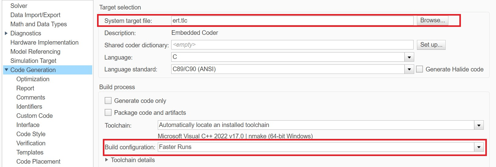
In Code Generation pane:
Set the System target file to ert.tlc.
Set the Build configuration to Faster Runs to prioritize execution speed.

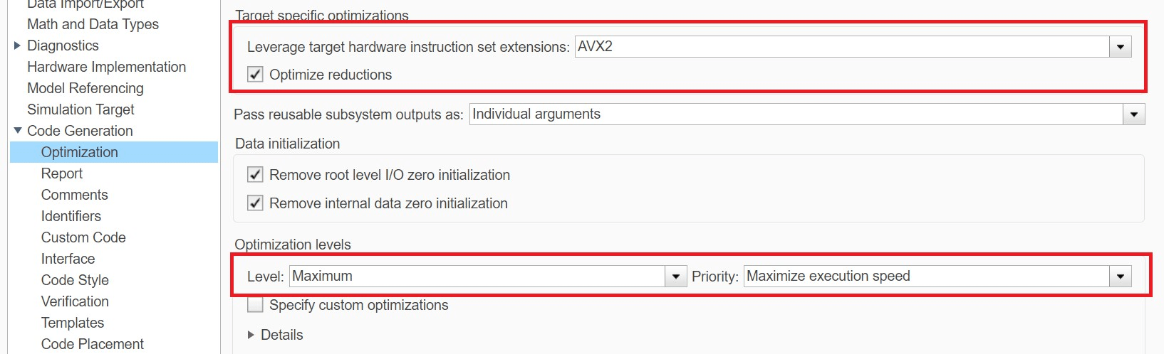
Under Code Generation, in the Optimization pane:
Set the Leverage target hardware instruction set extensions to AVX2.
Select the Optimize reductions option.
Set the Level to Maximum and Priority to Maximize execution speed to maximize the execution speed.
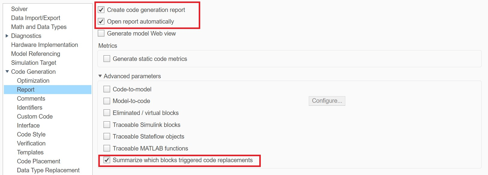
To see which blocks trigger code replacement, you can set the following options under Code Generation in the Report pane:
Enable Create code generation report.
Enable Open report automatically.
Enable Summarize which blocks triggered code replacements.
Use Programmatic Approach to Configure the Model
Alternatively, you can set all the configurations using set_param commands.
Set the Device vendor parameter to Intel. Set the Device type parameter to x86-64(Windows 64) or x86-64(Linux 64) based on your desktop environment.
if strcmp(computer('arch'),'win64')
    set_param(mdl,'ProdHWDeviceType','Intel->x86-64 (Windows64)');
elseif strcmp(computer('arch'),'glnxa64')
    set_param(mdl,'ProdHWDeviceType','Intel->x86-64 (Linux 64)');
end
Select ert.tlc as the system target file to optimize the code for embedded real-time systems, and choose Faster Runs for the build configuration to prioritize execution speed.
set_param(mdl,'SystemTargetFile','ert.tlc');
set_param(mdl,'BuildConfiguration','Faster Runs');
Set the code replacement libraries to none and set the instruction set to AVX2. Set the optimization level to level 2 (maximum) and optimization priority to maximum to maximize the execution speed.
set_param(mdl,'CodeReplacementLibrary','None');
set_param(mdl,'InstructionSetExtensions','AVX2');
set_param(mdl,'OptimizeReductions','On');
set_param(mdl,'OptimizationLevel','level2');
set_param(mdl,'OptimizationPriority','Speed');
Configure to generate the code generation report and show blocks that triggered code replacement.
set_param(mdl,'GenerateReport','On');
set_param(mdl,'LaunchReport','On');
set_param(mdl,'GenerateCodeReplacementReport','On');
To configure a Simulink model to generate SIMD code using the Intel AVX2 code replacement library, see Use Intel AVX2 Code Replacement Library to Generate SIMD Code from Simulink Blocks.
Simulate on Target Using SIL/PIL Manager
Use the SIL/PIL Manager app to simulate on target and to get the execution time of the generated code.
Follow these steps to perform SIL simulation:
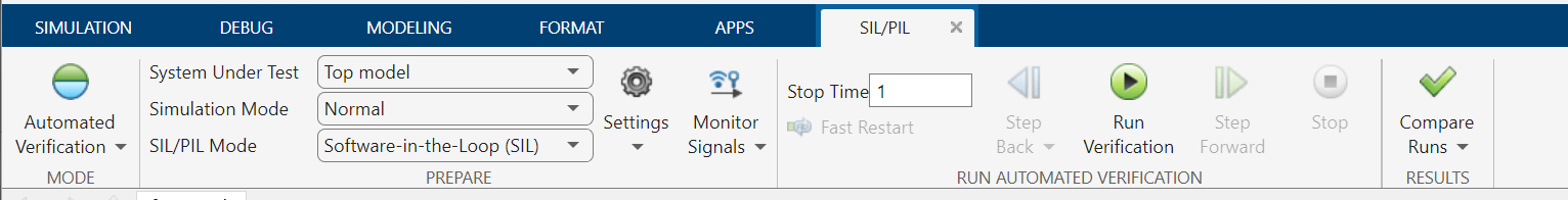
Go to Apps > SIL/PIL Manager.
Click Settings
Under Code Generation, in the Optimization pane, select the Specify custom optimizations and disable Generate parallel-for-loops
Set Mode to Automated Verification.
Set SIL/PIL Mode to Software-in-loop (SIL).
Click Run Verification.
Once the artifacts are built successfully, you can check replacements from the code generation report. Alternatively, you can execute the following command to run the SIL simulation.
set_param(mdl,'SimulationMode', 'software-in-the-loop (sil)');
set_param(mdl,'CodeExecutionProfiling','on');
set_param(mdl,'OptimizationCustomize','on');
set_param(mdl,'MultiThreadedLoops','off');
sim(mdl);
You can view the code execution metrics by clicking either Code Profile Analyzer or Code execution profiling report. The ifir_example_step1 in the report corresponds to the IFIR subsystem. To compare the performance of the generated code, use the value in Average Execution Time in ns column corresponding to ifir_example_step1.

Generate Code and Compare Performance
Use this interactive section to compare the performance of the generated code with the plain C code. Select the Instruction Set Extension or Intel AVX2 Code Replacement Library option to optimize the generated code from the drop-down list.
Note: Ensure that your processor supports the instruction set extension to avoid build errors.
compare ="AVX2";comparewith="None";
To get a better average, set the sample time of the Gaussian noise to 1 and stop time to 10000 so that the function is called 10001 times.
set_param([mdl,'/Gaussian Noise'],'SampTime','1');
set_param(mdl,'StopTime','10000');
set_param(mdl,'FixedStep','1');

if compare == "CRL"
    set_param(mdl,'InstructionSetExtensions','None');
    if strcmp(computer('arch'),'win64')
        set_param(mdl,'CodeReplacementLibrary','DSP Intel AVX2-FMA (Windows)');
    elseif strcmp(computer('arch'),'glnxa64')
        set_param(mdl,'CodeReplacementLibrary','DSP Intel AVX2-FMA (Linux)');
    end
else
    set_param(mdl,'InstructionSetExtensions',compare);
    set_param(mdl,'OptimizeReductions','On');
end

out = sim(mdl);
Get the total execution time of the generated SIMD code for comparison.
profileSectionIndex = 4;
tcompare = out.get('executionProfile').Sections(profileSectionIndex).TotalExecutionTimeInTicks;
Set the instruction set to none to generate code without SIMD instruction set extensions (plain C code).
if comparewith ~= "None"
    set_param(mdl,'InstructionSetExtensions',comparewith);
    set_param(mdl,'OptimizeReductions','On');
    set_param(mdl,'CodeReplacementLibrary','None');
else
    set_param(mdl,'InstructionSetExtensions',comparewith);
    set_param(mdl,'CodeReplacementLibrary','None');
end

out = sim(mdl);
Get the execution time of the generated plain C code for comparison.
tcomparewith = out.get('executionProfile').Sections(profileSectionIndex).TotalExecutionTimeInTicks;
close_system(mdl,0);
Compare the performance
performacegain = single(tcomparewith) ./ single(tcompare)
The AVX2 intrinsics achieve a performance gain of about 3.6x compared to plain C code. Note that all SIMD instruction set extensions show a performance gain of more than 3.2x and the Intel AVX2 Code Replacement Library shows a performance gain of 5.2x compared to plain C code.
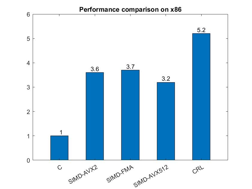
Note: To compare the performance, this example uses a Windows machine using an Intel Xeon(R) W-2133 CPU running at 3.60 GHz. These performance numbers might vary in your desktop environment.
See Also
FIR Decimation | FIR Interpolation | Discrete FIR Filter (Simulink)