Deploy Code for Battery State of Charge Estimation Using Deep Learning
This example shows how to deploy code for battery state of charge (SOC) estimation to hardware for processor-in-the-loop (PIL) testing.
SOC is the level of charge of an electric battery relative to its capacity, measured as a percentage. This example shows how to perform processor-in-the-loop (PIL) testing of the battery state of charge model.
In this example, you generate code and deploy it to an STM32 board. You then perform PIL testing by running the code on the processor, and transferring the results to Simulink® to verify the numerical equivalence of the simulation and the code generation results. The PIL verification process is a crucial part of the development cycle to ensure that the behavior of the deployment code matches the design. While this example uses an STM32 board, you can use Embedded Coder to generate C and C++ code optimized for many other embedded processors used in mass production.
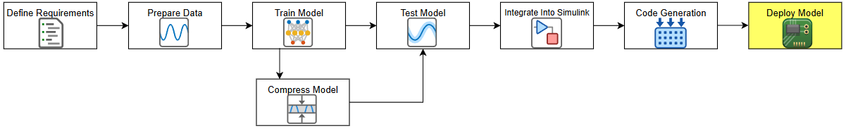
This example is in a series of examples that take you through a battery state of charge estimation workflow. You can run each step independently or work through the steps in order. This example follows the Generate Code for Battery State of Charge Estimation Using Deep Learning example. For more information about the full workflow, see Battery State of Charge Estimation Using Deep Learning.
Prerequisites
We recommend completing these tutorials:
Get Started with STMicroelectronics STM32 Processor Based Boards (STM32 Microcontroller Blockset)
Serial Configuration for Monitor & Tune and PIL for STM32 Processor-Based Boards (STM32 Microcontroller Blockset)
Required Hardware
STMicroelectronics® F7xx board
USB-A to micro-USB cable
Run Hardware Board Setup
Perform the hardware board setup process and configure the serial communication settings for PIL, as detailed in the prerequisite examples.
Load Trained Network
If you have run the previous steps, then the example uses the network that you trained. Otherwise, the example loads a network trained as in Train Deep Learning Network for Battery State of Charge Estimation and compressed in Compress Deep Learning Network for Battery State of Charge Estimation.
if ~exist("recurrentNet","var")
    load("pretrainedBSOCNetworkCompressed.mat")
end
The network has been trained to predict battery SOC given three inputs: temperature, voltage, and current. The network has been trained on data taken at four different ambient temperatures: -10, 0, 10, and 25 degrees Celsius.
Open Simulink Model
Open a Simulink model for battery state of charge estimation. This model contains a subsystem with an AI component. In this example, the AI component is a trained LSTM network that can predict the state of charge given temperature, voltage, and current inputs.
open_system("BatterySOCEstimationDeepLearning")Prepare the test data using the prepareSimulinkBSOCTestData function, attached to this example as a supporting file. This function prepares the data as shown in the Integrate AI Model into Simulink for Battery State of Charge Estimation example.
[steps,Ts,ds] = prepareSimulinkBSOCTestData;
set_param("BatterySOCEstimationDeepLearning", ...
    StopTime="steps", ...
    LoadExternalInput="on", ...
    ExternalInput="ds", ...
    FixedStep="Ts")
PIL Simulation
A PIL simulation cross-compiles the generated code for the target processor and then downloads and runs the application on the target. With PIL simulation on a target board, you can:
Verify behavior of target-specific code.
Optimize the execution speed and memory footprint of your code.
Investigate effects of compiler settings and optimizations.
In contrast, software-in-the-loop (SIL) testing does not account for restrictions and requirements that the hardware imposes, such as limited memory resources or behavior of target-specific optimized code.
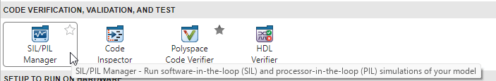
On the Apps tab, click SIL/PIL Manager.
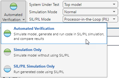
In the Mode section, select Automated Verification. When you select Automated Verification, the SIL/PIL Manager app will run two simulations back-to-back and then use the Data Inspector to compare the results. The first simulation is a model simulation and the second simulation is PIL or SIL simulation.
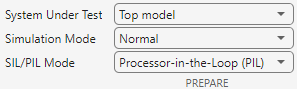
In the Prepare section, set System Under Test to Top model. In the SIL/PIL Mode field, select Processor-in-the-Loop (PIL).
Click Run Verification.
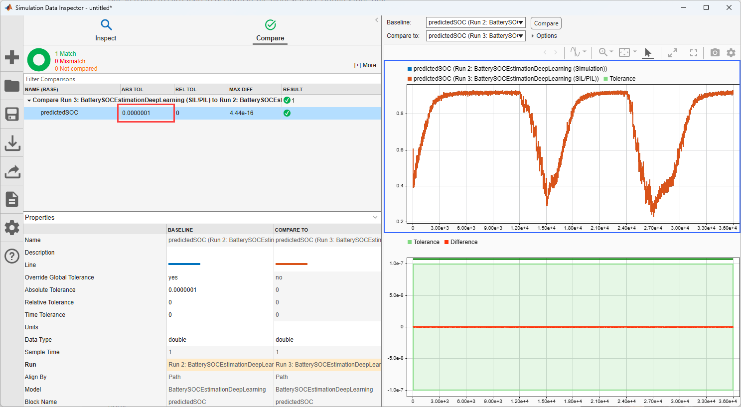
View Results
At the end of the simulation, the Data Inspector opens and compares the Simulation and PIL results. In the table, set ABS TOL to 1e-7. This setting specifies the allowable difference between the signals from the simulation and the processor.
Link PIL Requirements Using Requirements Toolbox
This section verifies the PIL testing requirements and requires Requirements Toolbox™ and Simulink® Test™. This section does not show how to create or link requirements, only how to implement and verify the links. For more information about defining these requirements, see Define Requirements for Battery State of Charge Estimation.
For general information about how to create and manage requirements, see Use Requirements to Develop and Verify MATLAB Functions (Requirements Toolbox).
Linking SIL testing requirements is important for ensuring the AI model behaves as expected once you have generated code.
Check for a Requirements Toolbox™ license.
if ~license("test","simulink_requirements")
    disp("This part of the example requires Requirements Toolbox.");
    return
end
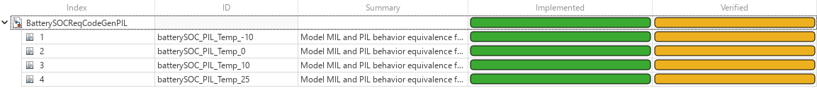
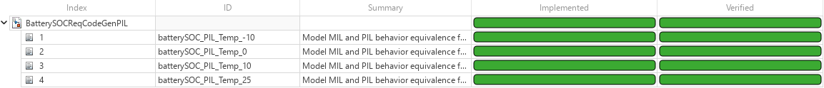
Open the PIL requirements. To add columns that indicate the implementation status and verification status of the requirements, click Columns ![]() and then select Implementation Status and Verification Status. If you see a yellow banner, then click Analyze now. You can see each of the requirements and their implementation status and verification status. The verification status for each requirement is yellow, indicating that the status is unknown. The status turns to red if the requirement fails or green if the requirement passes.
and then select Implementation Status and Verification Status. If you see a yellow banner, then click Analyze now. You can see each of the requirements and their implementation status and verification status. The verification status for each requirement is yellow, indicating that the status is unknown. The status turns to red if the requirement fails or green if the requirement passes.
slreq.open("BatterySOCReqCodeGenPIL.slreqx");
load_system("BatterySOCEstimationDeepLearning.slx")
sltest.testmanager.load("BSOCSimulinkIntegrationTestPIL.mldatx");
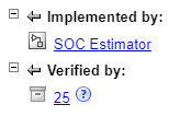
Select one of the requirements. Each requirement is implemented by the SOC Estimator subsystem and verified by a test.
Implement Requirements
PIL testing ensures that the behavior of the deployment code matches the design. For example, you can test numerical equivalence between the model and the code running on the processor.
Verify Requirements
The next step is to formally verify the requirements. To verify requirements, create tests to check that the PIL results match the result of the Simulink simulation. You can find the PIL tests in the BSOCSimulationIntegrationTestPIL file, attached to this example as a supporting file. The tests check that, for each temperature, the difference between the Simulink simulation and the PIL test is within a certain tolerance.

Before you can run the PIL test, you must first generate code for the top model. To build the model and generate code, follow the previous steps or use Ctrl+B in the Simulink canvas.
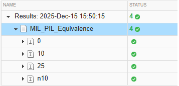
To run the tests, open Test Manager with BSOCSimulationIntegrationTestPIL. Select MIL_PIL_Equivalence. This test checks that the PIL test and the Simulink model are within 1e-7 of each other. To run the test, click Run.
The test passes for each temperature. You can adjust the test tolerance to match the requirements of your system.
In Requirements Editor, you can see that the verification status is now green (Passed).
As a next step, you can use the Code Profile Analyzer (Embedded Coder) to analyze execution-time and stack usage profiles for your generated code. For more information, see View and Compare Code Execution Times (Embedded Coder) and View and Compare Stack Usage Metrics (Embedded Coder).
See Also
SIL/PIL Manager (Embedded Coder) | Requirements Editor (Requirements Toolbox) | Code Profile Analyzer (Embedded Coder)