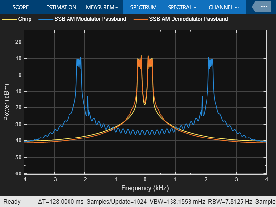
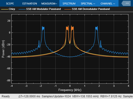
SSB AM Modulator Passband
Modulate using single-sideband amplitude modulation
Library
Analog Passband Modulation, in Modulation
Description
The SSB AM Modulator Passband block modulates using single-sideband amplitude modulation with a Hilbert transform filter. The output is a passband representation of the modulated signal. Both the input and output signals are real scalar signals.
SSB AM Modulator Passband transmits either the lower or upper sideband signal, but not both. To control which sideband it transmits, use the Sideband to modulate parameter.
If the input is u(t) as a function of time t, then the output is
where:
fc is the Carrier frequency parameter.
θ is the Initial phase parameter.
û(t)is the Hilbert transform of the input u(t).
The minus sign indicates the upper sideband and the plus sign indicates the lower sideband.
Hilbert Transform Filter
This block uses the Analytic Signal block from the DSP System Toolbox™ Transforms block library.
The Analytic Signal block computes the complex analytic signal corresponding to each channel of the real M-by-N input, u
where and denotes the Hilbert transform. The real part of the output in each channel is a replica of the real input in that channel; the imaginary part is the Hilbert transform of the input. In the frequency domain, the analytic signal retains the positive frequency content of the original signal while zeroing-out negative frequencies and doubling the DC component.
The block computes the Hilbert transform using an equiripple FIR filter with the order specified by the Filter order parameter, n. The linear phase filter is designed using the Remez exchange algorithm, and imposes a delay of n/2 on the input samples.
For best results, use a carrier frequency which is estimated to be larger than 10% of your input signal's sample rate. This is due to the implementation of the Hilbert transform by means of a filter.
In the following example, we sample a 10Hz input signal at 8000 samples per
second. We then designate a Hilbert Transform filter of order 100. Below is the
response of the Hilbert Transform filter as returned by
fvtool
.
Note the bandwidth of the filter's magnitude response. By choosing a carrier frequency larger than 10% (but less than 90%) of the input signal's sample time (8000 samples per second, in this example) or equivalently, a carrier frequency larger than 400Hz, we ensure that the Hilbert Transform Filter will be operating in the flat section of the filter's magnitude response (shown in blue), and that our modulated signal will have the desired magnitude and form.
Typically, an appropriate Carrier frequency value is much higher than the highest frequency of the input signal. By the Nyquist sampling theorem, the reciprocal of the model's sample time (defined by the model's signal source) must exceed twice the Carrier frequency parameter.
This block works only with real inputs of type double
. This
block does not work inside a triggered subsystem.
Parameters
- Carrier frequency (Hz)
The frequency of the carrier.
- Initial phase (rad)
The phase offset, , of the modulated signal.
- Sideband to modulate
This parameter specifies whether to transmit the upper or lower sideband.
- Hilbert Transform filter order
The length of the FIR filter used to compute the Hilbert transform.
Pair Block
References
[1] Peebles, Peyton Z, Jr. Communication System Principles. Reading, Mass.: Addison-Wesley, 1976.
Extended Capabilities
Version History
Introduced before R2006a