メインコンテンツ

reflectorCalculator

Create parabolic reflector antenna for Gaussian beam analysis

Since R2026a

    Description

    The default reflectorCalculator object creates a horn-fed parabolic reflector antenna with 1 m reflector diameter.

    Specify geometric and feed parameters, choose from single, array, or custom pattern feeds, and analyze key performance metrics at your target frequencies. Visualize antenna layout and radiation patterns to streamline early-stage design and trade studies, optimize feed illumination, and maximize antenna efficiency without the need for full-wave simulation.

    Creation

    Description

    r = reflectorCalculator creates a horn-fed parabolic reflector antenna with default property values.

    example

    r = reflectorCalculator(PropertyName=Value) sets properties using one or more name-value arguments. PropertyName is the property name and Value is the corresponding value. You can specify several name-value arguments in any order as PropertyName1=Value1,...,PropertyNameN=ValueN. Properties that you do not specify, retain their default values.

    For example, r = reflectorCalculator(Diameter=2) creates a parabolic reflector antenna with a reflector diameter of 2 m and default values for other properties.

    Properties

    expand all

    Diameter of the reflector, specified as a positive scalar in meters.

    Example: 2

    Data Types: double

    Focal length of the reflector, specified as a positive scalar in meters.

    Example: 0.5

    Data Types: double

    Offset height of the reflector from the base or the reference axis, specified as a nonnegative scalar in meters.

    Example: 0.3

    Data Types: double

    Type of radiating element for the reflector, specified as one of the following:

    • "singlefed" — Single radiating element

    • "arrayfed" — Array of radiating elements

    • "patternfed" — Pattern data of radiating elements

    Example: "patternfed"

    Data Types: char | string

    Radiating element of the reflector, specified as one of the following:

    • "horn" — A rectangular horn antenna created using the horn object

    • "conicalhorn" — A conical horn antenna created using the hornConical object

    • "corrugatedhorn" — A rectangular corrugated-horn antenna created using the hornCorrugated object

    • "potterhorn" — A Potter horn antenna created using the hornPotter object

    Example: "conicalhorn"

    Data Types: char | string

    Aperture of the radiating element, specified as a positive scalar in meters.

    Example: 0.07

    Data Types: double

    Number of radiating elements, specified as a positive integer. You can specify this property when you set the FeedType property to "arrayfed".

    Example: 4

    Data Types: double

    Spacing between the radiating elements, specified as a positive scalar in meters. You can specify this property when you set the FeedType property to "arrayfed".

    Example: 0.2

    Data Types: double

    Name of the radiation pattern data file with extension, specified as a string or a character vector. You can also specify a full path to the file. This property supports only .txt and .csv files.

    On Microsoft® Windows® systems, you can use either forward slashes (/) or backslashes (\) as path delimiters, even within the same file name. On UNIX® and Macintosh systems, use only a / as a delimiter. You can specify this property when you set the FeedType property to "patternfed".

    Example: "pattern_data.txt"

    Data Types: char | string

    Angular deviation of the main beam from the boresight direction, specified as a positive scalar in degrees.

    Example: 30

    Data Types: double

    Root-mean-square deviation of the reflector from its ideal shape, specified as a scalar in meters. Typical surface error values are on the order of millimeters.

    Example: 0.001

    Data Types: double

    Loss associated with the radiating element, specified as a nonnegative scalar in dB.

    Example: 1

    Data Types: double

    Object Functions

    createAntennaCreate dual-reflector antenna for full-wave analysis
    peakDirectivityCalculate maximum directivity
    plotVisualize antenna layout and plot directivity, beamwidth, and efficiency
    solveAnalyze antenna using Gaussian-beam method

    Examples

    collapse all

    Design a horn-fed offset parabolic reflector antenna with a 1 m diameter, 0.9 m focal length, 0.1 m clearance height, 68 mm radiator aperture, and a 1 mm surface error.

    ant = reflectorCalculator(Diameter=1,FocalLength=0.9,ClearanceHeight=0.1, ...
        RadiatorAperture=68e-3,SurfaceError=1e-3);

    Analyze this antenna at 10 GHz.

    solve(ant,10e9);
    Here is the output for your entered data: 
                                                           Reflector Antenna Values
                                                           ________________________
    
        Focal Length (λ)                                             30.02         
        Clearance Height (λ)                                          3.34         
        Diameter (λ)                                                 33.36         
        Feed Tilt Angle θ* (°)                                       36.87         
        Half Angle Subtended By Reflector Center θ_0(°)              28.25         
        Angle At Bottom Edge θ1 (°)                                   6.36         
        Angle At Top Edge θ2 (°)                                     62.86         
        Efficiency (%)                                               75.35         
        Peak Directivity at Boresight Beam (dBi)                     39.18         
        Gain at Boresight Beam (dBi)                                 37.65         
        Gain at Scan Angle (dBi)                                     37.63         
        Illumination Taper (dB)                                      16.29         
        Half Power Beamwidth (°)                                      2.12         
        Feed Size (m)                                                 0.07         
        First SLL (dB)                                              -33.54         
        Gain Loss due to Worst Case Scan (dB)                         0.02         
        Loss due to Surface RMS and Thermal (dB)                      0.76         
        Feed Loss (dB)                                                   0         
    

    Visualize the layout and analyze the directivity and beamwidth with reference to the variation in the diameter.

    figure
    plot(ant,Type="layout");
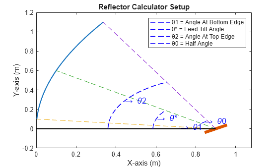
    Figure contains an axes object. The axes object with title Reflector Calculator Setup, xlabel X-axis (m), ylabel Y-axis (m) contains 14 objects of type line, text. These objects represent θ1 = Angle At Bottom Edge, θ* = Feed Tilt Angle, θ2 = Angle At Top Edge, θ0 = Half Angle.

    figure
    plot(ant,Frequency=10e9,Type="directivity");
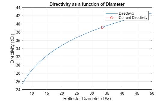
    Figure contains an axes object. The axes object with title Directivity as a function of Diameter, xlabel Reflector Diameter (D/λ), ylabel Directivity (dBi) contains 2 objects of type line. These objects represent Directivity, Current Directivity.

    figure
    plot(ant,Frequency=10e9,Type="beamwidth");

    Figure contains an axes object. The axes object with title 3dB Beamwidth as a function of Diameter, xlabel Reflector Diameter (D/λ), ylabel 3-dB Beamwidth (°) contains 2 objects of type line. These objects represent 3-dB Beamwidth, Current BeamWidth.

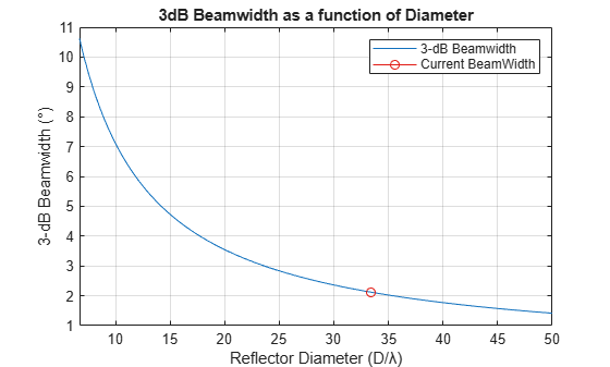
    Calculate the peak directivity of the reflector antenna.

    peakDirectivity(ant,10e9);
    39.177266 dBi 
    

    Design an offset parabolic reflector antenna with a 1.2 m diameter, 0.8 m focal length, and a 0.6 m clearance height fed by a four-element conical horn array with a 0.065 m aperture and 0.07 m element spacing.

    r = reflectorCalculator(Diameter=1.2,FocalLength=0.8,ClearanceHeight=0.6,RadiatorAperture=0.065, ...
        RadiatingElement="horn",FeedType="arrayfed",NumRadiators=4,Spacing=0.07);

    Analyze the reflector antenna at 10 GHz.

    solve(r,10e9);
    Here is the output for your entered data: 
                                                           Reflector Antenna Values
                                                           ________________________
    
        Focal Length (λ)                                             26.69         
        Clearance Height (λ)                                         20.01         
        Diameter (λ)                                                 40.03         
        Feed Tilt Angle θ* (°)                                       73.74         
        Half Angle Subtended By Reflector Center θ_0(°)              27.81         
        Angle At Bottom Edge θ1 (°)                                  41.11         
        Angle At Top Edge θ2 (°)                                     96.73         
        Efficiency (%)                                               25.27         
        Peak Directivity at Boresight Beam (dBi)                     36.02         
        Gain at Boresight Beam (dBi)                                 36.02         
        Gain at Scan Angle (dBi)                                     35.95         
        Illumination Taper (dB)                                      66.91         
        Half Power Beamwidth (°)                                      2.73         
        Feed Size (m)                                                 0.07         
        First SLL (dB)                                              -208.4         
        Gain Loss due to Worst Case Scan (dB)                         0.06         
        Loss due to Surface RMS and Thermal (dB)                         0         
        Feed Loss (dB)                                                   0         
    

    Visualize the antenna setup layout.

    plot(r,Type="layout");

    Figure contains an axes object. The axes object with title Reflector Calculator Setup, xlabel X-axis (m), ylabel Y-axis (m) contains 14 objects of type line, scatter, text. These objects represent θ1 = Angle At Bottom Edge, θ* = Feed Tilt Angle, θ2 = Angle At Top Edge, θ0 = Half Angle.

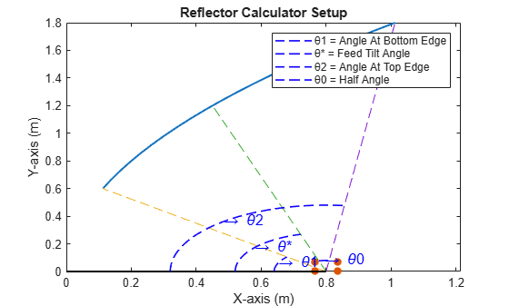
    Design an offset parabolic reflector with a 1.2 m diameter, 1 m focal length, 0.65 m clearance height, and use pattern data to feed the reflector. Analyze the antenna at 12 GHz.

    ant = reflectorCalculator(Diameter=1.2,FocalLength=1,ClearanceHeight=0.65,FeedType="patternfed", ...
        FileName="corrugated_horn_12ghz_pattern_data.txt");
    solve(ant,12e9);
    Here is the output for your entered data: 
                                                           Reflector Antenna Values
                                                           ________________________
    
        Focal Length (λ)                                             40.03         
        Clearance Height (λ)                                         26.02         
        Diameter (λ)                                                 48.03         
        Feed Tilt Angle θ* (°)                                       64.01         
        Half Angle Subtended By Reflector Center θ_0(°)              24.76         
        Angle At Bottom Edge θ1 (°)                                  36.01         
        Angle At Top Edge θ2 (°)                                     85.54         
        Efficiency (%)                                               77.67         
        Peak Directivity at Boresight Beam (dBi)                     42.48         
        Gain at Boresight Beam (dBi)                                 42.48         
        Gain at Scan Angle (dBi)                                     42.34         
        Illumination Taper (dB)                                      14.87         
        Half Power Beamwidth (°)                                      1.45         
        Feed Size (m)                                                 0.07         
        First SLL (dB)                                              -31.38         
        Gain Loss due to Worst Case Scan (dB)                         0.14         
        Loss due to Surface RMS and Thermal (dB)                         0         
        Feed Loss (dB)                                                   0         
    

    Plot the pattern data for the reflector antenna.

    plot(ant,Frequency=12e9,Type="patterndata");
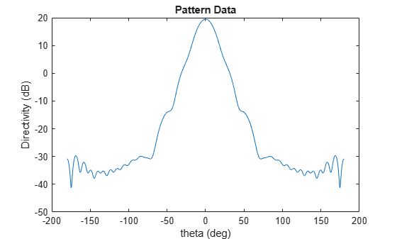
    Figure contains an axes object. The axes object with title Pattern Data, xlabel theta (deg), ylabel Directivity (dB) contains an object of type line.

    Version History

    Introduced in R2026a

    See Also

    Objects