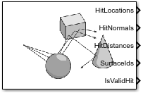
Simulation 3D Ray Tracer
Libraries:
Vehicle Dynamics Blockset /
Vehicle Scenarios /
Sim3D /
Sim3D Vehicle /
Components
Simulink 3D Animation /
Simulation 3D /
Sensors
Description
Note
Simulating models with the Simulation 3D Ray Tracer block requires Simulink® 3D Animation™.
The Simulation 3D Ray Tracer block implements ray tracing to get the positions, surface normals, surface identifiers, and distances for objects in the scene. You can specify block parameters that configure the ray origins, directions, and lengths to adjust the ray trace sensor pattern for your scene and test scenario.
Tip
Verify that the Simulation 3D Scene
Configuration block executes before the Simulation 3D Ray Tracer block. That way, the
Unreal Engine® 3D visualization environment prepares the data before the Simulation 3D Ray Tracer block
receives it. To check the block execution order, right-click the blocks and then click the
Properties button ![]() . On the General tab, confirm these
Priority settings:
. On the General tab, confirm these
Priority settings:
Simulation 3D Scene Configuration —
0Simulation 3D Terrain Sensor —
1
For more information about execution order, see Control and Display Execution Order.
The Coordinate system parameter of the block specifies how the actor transformations are applied in the 3D environment. The output of the block also follows the specified coordinate system.
Ports
Output
Hit locations, returned as a real-valued N(B+1)-by-3 array of the form [X, Y, Z], in meters. N is the number of rays and B is the number of bounces per ray.
If you mount the sensor to a vehicle by setting Parent name to the name of that vehicle, then X, Y, and Z coordinates are defined in the coordinate system specified by the Coordinate system parameter.
Data Types: double
Ray normal to the hit location, returned as a real-valued N(B+1)-by-3 array of the form [X, Y, Z], in meters. N is the number of rays and B is the number of bounces per ray.
If you mount the sensor to a vehicle by setting Parent name to the name of that vehicle, then X, Y, and Z coordinates are defined in the coordinate system specified by the Coordinate system parameter.
Data Types: double
Ray distance to hit location, returned as a real-valued N(B+1)-by-1 vector N, in meters. N is the number of rays and B is the number of bounces per ray.
Data Types: double
Object identifier of the surfaces hit by the ray, returned as an integer-valued N(B+1)-by-1 vector N. N is the number of rays and B is the number of bounces per ray.
The returned surface identifiers are the object values specified when creating
custom surfaces in the Unreal® Editor. If a surface identifier is unknown, the block assigns it an ID
of 0. For information about adding surfaces, see Add a Surface Type in the Unreal Engine documentation.
Data Types: uint8
Hit flag, returned as a N-by-1 Boolean vector. N is the number of rays. A value of 1 indicates the ray hit a surface.
Data Types: Boolean
Parameters
Mounting
Specify the unique identifier of the sensor. In a multisensor system, the sensor identifier enables you to distinguish between sensors. When you add a new sensor block to your model, the Sensor identifier of that block is N + 1, where N is the highest Sensor identifier value among the existing sensor blocks in the model.
Example: 2
Specify the name of the parent to which the sensor is mounted. The block provides a
list of parent actors in the model. The names that you can select correspond to the
values of the Name parameters of the Simulation 3D
blocks in your model. If you select Scene Origin, the block
places a sensor at the scene origin. The Custom option allows
you to specify the name of any actor, including child actors in the environment, as the
parent actor.
Example: SimulinkVehicle1
Specify the name of custom parent. This parameter allows you to set any actor in the environment, including child actors as the parent actor to which the sensor is mounted. The name corresponds to the Name parameter of the Simulation 3D block.
Example: SimulinkVehicle1
Dependencies
To enable this parameter, set Parent name to
Custom.
Specify the coordinate system that the actor uses for translation and rotation in the 3D environment.
Default– World coordinate system. Units are in m and rad.MATLAB– MATLAB® coordinate system. Units are in m and rad.ISO8855– ISO 8855 standard coordinate system. Units are in m and deg.AERO– SAE coordinate system. Units are in m and rad.VRML– X3D ISO standard coordinate system. Units are in m and rad.SAE– SAE coordinate system. Units are in m and rad.
For more details on the different coordinate systems, see Actor Coordinate Systems.
Example: MATLAB
Sensor mounting location. By default, the block places the sensor relative to the scene or vehicle origin, depending on the Parent name parameter.
When Parent name is
Scene
                            Origin
, the block mounts the sensor to the origin of the scene. You can set the Mounting location toOriginonly. During simulation, the sensor remains stationary.When Parent name is
sim3dactor name, the block mounts the sensor to the origin of the actor, which is the center of the shape. You can set the Mounting location toOriginonly. During simulation, the sensor travels with the actor.When Parent name is the name of a vehicle, the block mounts the sensor to one of the predefined mounting locations described in the table. During simulation, the sensor travels with the vehicle.
| Mounting Location | Description | Orientation Relative to Vehicle Origin [Roll, Pitch, Yaw] (deg) |
|---|---|---|
Origin | Forward-facing sensor mounted to the vehicle origin, which is on the ground and at the geometric center of the vehicle (see Coordinate Systems in Vehicle Dynamics Blockset) | [0, 0, 0] |
| Forward-facing sensor mounted to the front bumper | [0, 0, 0] |
| Backward-facing sensor mounted to the rear bumper | [0, 0, 180] |
Right mirror | Downward-facing sensor mounted to the right side-view mirror | [0, –90, 0] |
Left mirror | Downward-facing sensor mounted to the left side-view mirror | [0, –90, 0] |
Rearview mirror | Forward-facing sensor mounted to the rearview mirror, inside the vehicle | [0, 0, 0] |
Hood center | Forward-facing sensor mounted to the center of the hood | [0, 0, 0] |
Roof center | Forward-facing sensor mounted to the center of the roof | [0, 0, 0] |
Roll, pitch, and yaw are clockwise-positive when looking in the positive direction of the X-axis, Y-axis, and Z-axis, respectively. When looking at a vehicle from above, the yaw angle (the orientation angle) is counterclockwise-positive because you are looking in the negative direction of the axis.
To determine the location of the sensor, open the sensor block. Then, on the Ground Truth tab, select the Output location and orientation parameter and inspect the data from the Translation output port.
Select this parameter to specify an offset from the mounting location by using the Relative translation [X, Y, Z] and Relative rotation [Roll, Pitch, Yaw] parameters.
Translation offset relative to the mounting location of the sensor, specified as a real-valued 1-by-3 vector of the form [X, Y, Z], in meters.
You can mount the sensor to a vehicle by setting Parent name to
the name of that vehicle, then X, Y, and
Z coordinates are defined in the coordinate system specified by
the Coordinate system parameter. The origin is the mounting
location specified in the Mounting location parameter. This origin
is different from the vehicle origin, which is the geometric center of the vehicle. You
can also mount the sensor to the scene origin by setting Parent
name to Scene Origin.
For more details about the vehicle and world coordinate systems, see Coordinate Systems in Vehicle Dynamics Blockset.
Example: [0,0,0.01]
Dependencies
To enable this parameter, select Specify offset.
Rotational offset relative to the mounting location of the sensor, specified as a real-valued 1-by-3 vector of the form [Roll, Pitch, Yaw]. Roll, pitch, and yaw are the angles of rotation about the X-, Y-, and Z-axes, respectively.
You can mount the sensor to a vehicle by setting Parent name to
the name of that vehicle, then X, Y, and
Z coordinates are defined in the coordinate system specified by
the Coordinate system parameter. The origin is the mounting
location specified in the Mounting location parameter. This origin
is different from the vehicle origin, which is the geometric center of the vehicle. You
can also mount the sensor to the scene origin by setting Parent
name to Scene Origin. The rotation order is
Roll, then Pitch, then
Yaw. When you update any of the three rotation values and leave
others unchanged, the software reapplies all three rotations in the same order.
For more details about the vehicle and world coordinate systems, see Coordinate Systems in Vehicle Dynamics Blockset.
Example: [0,0,10]
Dependencies
To enable this parameter, select Specify offset.
Parameters
Ray origin relative to sensor mounting location, specified as a real-valued N-by-3 array of the form [X, Y, Z], in meters. N is the number of rays.
If you mount the sensor to a vehicle by setting Parent name to the name of that vehicle, then X, Y, and Z are in the world coordinate system, where:
The X-axis points forward from the vehicle
The Y-axis points to the right of the vehicle, as viewed when looking in the forward direction of the vehicle
The Z-axis points up
Example: zeros(10,3)
Normalized ray direction relative to sensor mounting location, specified as a real-valued N-by-3 array of the form [X, Y, Z]. N is the number of rays. The units are dimensionless.
If you mount the sensor to a vehicle by setting Parent name to the name of that vehicle, then X, Y, and Z are in the world coordinate system, where:
The X-axis points forward from the vehicle
The Y-axis points to the right of the vehicle, as viewed when looking in the forward direction of the vehicle
The Z-axis points up
Example: ones(10,3)
Maximum total ray length of a multi-bounce trace path, specified as a real-valued N-by-1 vector, in meters. N is the number of rays.
Example: ones(10,1)*10
Number of bounces that a trace may have before terminating, B, specified as an integer.
Example: 0
Whether to enable Unreal Engine trace line visualization for the ray tracer.
Whether to enable optimization of the ray tracer. Enabling this parameter allows the block to perform concurrent traces. Enable this parameter when the number of traces is large and your machine has multiple cores.
Sample time of the block, in seconds, specified as a positive scalar. The 3D simulation environment frame rate is the inverse of the sample time.
If you set the sample time to -1, the block inherits its sample time from
the Simulation 3D Scene Configuration block.
Version History
Introduced in R2022bSet the Coordinate system parameter in the Simulation 3D Ray Tracer block to represent the coordinate system for actor transformation in the 3D environment.
Setting the Parent name to
Custom enables the Custom parent name parameter,
with which you can specify the name of the actor to which you want to mount the sensor.
Simulating models with the Simulation 3D Ray Tracer block requires Simulink 3D Animation.
MATLAB Command
You clicked a link that corresponds to this MATLAB command:
Run the command by entering it in the MATLAB Command Window. Web browsers do not support MATLAB commands.
Web サイトの選択
Web サイトを選択すると、翻訳されたコンテンツにアクセスし、地域のイベントやサービスを確認できます。現在の位置情報に基づき、次のサイトの選択を推奨します:
また、以下のリストから Web サイトを選択することもできます。
最適なサイトパフォーマンスの取得方法
中国のサイト (中国語または英語) を選択することで、最適なサイトパフォーマンスが得られます。その他の国の MathWorks のサイトは、お客様の地域からのアクセスが最適化されていません。
南北アメリカ
- América Latina (Español)
- Canada (English)
- United States (English)
ヨーロッパ
- Belgium (English)
- Denmark (English)
- Deutschland (Deutsch)
- España (Español)
- Finland (English)
- France (Français)
- Ireland (English)
- Italia (Italiano)
- Luxembourg (English)
- Netherlands (English)
- Norway (English)
- Österreich (Deutsch)
- Portugal (English)
- Sweden (English)
- Switzerland
- United Kingdom (English)