uavCoverageSpace
Description
The uavCoverageSpace object represents the coverage space as a set of
convex polygons to use with the uavCoveragePlanner to
perform coverage planning. Given a coverage area, the polygons form its configuration
space.
Creation
Syntax
Description
space = uavCoverageSpace creates an empty coverage space with
default properties.
space = uavCoverageSpace(Polygons=
creates a coverage space defined by convex one or more convex polygons as vertices
polygonVertices)polygonVertices, and sets the Polygons
property.
space = uavCoverageSpace(___,
sets properties using one or more name-value arguments. For example,
Name=Value)uavCoverageSpace(Overlap=0.5) sets the Overlap
property to 0.5.
Input Arguments
Convex polygons to survey, specified as an M-by-2 matrix or an N-element cell array of M-by-2 matrices. N is the total number of polygons, and M is the total number of vertices that define the polygon.
Concave polygons must be decomposed into convex polygons using the coverageDecomposition function.
The format of the vertices depends on the UseLocalCoordinates property:
UseLocalCoordinates=true— Format is local xy-coordinates in the form [x y], in meters.UseLocalCoordinatesis true by default.UseLocalCoordinates=false— Format is geodetic coordinates in the form [latitude longitude]. latitude and longitude are in degrees.
Note
If you enable UseLocalCoordinates, you must specify a polygon
that has a maximum perpendicular distance from any vertex to a non-adjacent edge of
less than 20 km to satisfy the flat Earth approximation.
Example: {[0 0; 0 1; 1 1; 1 0],[1 1; 2 2; 3 1]}
Data Types: single | double
Properties
Polygons to survey, specified as a N-element row vector of
structures. N is the total number of polygons specified in the
polygons argument. Each structure contains the
Vertices and SweepAngle:
Vertices— Vertices that define the polygon, specified as an M-by-2 matrix. M is the total number of vertices.The format of the vertices depends on the
UseLocalCoordinatesproperty:UseLocalCoordinates=true— Format is local xy-coordinates in the form [x y], in meters.UseLocalCoordinatesis true by default.UseLocalCoordinates=false— Format is geodetic coordinates in the form [latitude longitude]. latitude and longitude are in degrees.
SweepAngle— Angle at which the UAV sweeps the polygon, specified as numeric scalar, in degrees. This value is NaN by default until you specify it or until the solver algorithm determines it when you plan the path with theuavCoveragePlannerobject.
Overlap between sensor footprints in a single row, specified as a nonnegative
numeric scalar in the range [0, 1). A value of 0 specifies that the
sensor footprints have no overlap, and a value of 1 indicates that
the sensor footprints fully overlap.
Data Types: single | double
Overlap between sensor footprints of two rows, specified as a nonnegative numeric
scalar in the range [0, 1]. A value of 0 specifies that the sensor
footprints have no sidelap, and a value of 1 specifies that the
sensor footprints fully sidelap.
Data Types: single | double
Width of sensor footprint, specified as a positive numeric scalar, in meters. This measurement is along the sweep line direction.
Data Types: single | double
Length of sensor footprint, specified as a positive numeric scalar, in meters. This measurement is perpendicular to the sweep line direction.
Data Types: single | double
Flight altitude of UAV, specified as a nonnegative numeric scalar, in meters.
When UseLocalCoordinates is true or
1, the reference height is with respect to the local reference
frame. When UseLocalCoordinates is false or
0, the coverage space assumes a flat-Earth approximation and the
reference height is with respect to the ground at absolute zero meters.
Data Types: single | double
Use local coordinate or geodetic coordinate format, specified as
true for local coordinate format or false for
geodetic coordinate format.
When
UseLocalCoordinatesistrue:Vertices of polygons in the
uavCoverageSpaceare specified as xy-coordinates in the form [x y], in meters.takeoffandlandingpositions are specified as xyz-coordinates in the form [x y z], in meters.Planned waypoints are returned as xyz-coordinates in the form [x y z], in meters.
When
UseLocalCoordinatesisfalse:Vertices of polygons in the
uavCoverageSpaceare specified as geodetic coordinates in the form [latitude longitude]. latitude and longitude are in degrees.takeoffandlandingpositions are specified as geodetic coordinates in the form [latitude longitude altitude]. latitude and longitude are in degrees, and altitude is in meters.Planned waypoints are returned as geodetic coordinates in the form [latitude longitude altitude]. latitude and longitude are in degrees, and altitude is in meters.
Georeference to compute and export to geodetic waypoint coordinates, specified as an three-element row vector of the form [latitude longitude altitude]. latitude and longitude are in degrees, and altitude is in meters.
Data Types: double
Object Functions
setCoveragePattern | Set sweep angle for polygon in coverage area |
show | Visualize 2D coverage space |
Examples
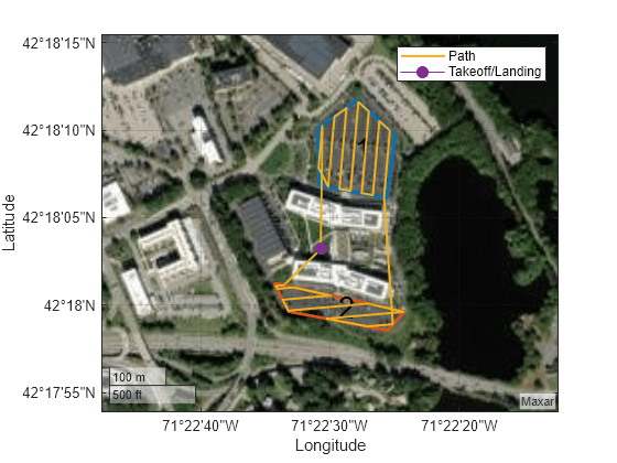
This example shows how to plan a coverage path that surveys the parking lots of the MathWorks Lakeside campus.
Get the geodetic coordinates for the MathWorks Lakeside campus. Then create the limits for our map.
mwLS = [42.3013 -71.375 0];
latlim = [mwLS(1)-0.003 mwLS(1)+0.003];
lonlim = [mwLS(2)-0.003 mwLS(2)+0.003];
Create a figure containing the map with the longitude and latitude limits.
fig = figure;
g = geoaxes(fig,Basemap="satellite");
geolimits(latlim,lonlim)
Get the outline of the first parking lot in longitude and latitude coordinates. Then create the polygon by concatenating them.
pl1lat = [42.3028 42.30325 42.3027 42.3017 42.3019]';
pl1lon = [-71.37527 -71.37442 -71.3736 -71.37378 -71.375234]';
pl1Poly = [pl1lat pl1lon];
Repeat the process for the second parking lot.
pl2lat = [42.30035 42.2999 42.2996 42.2999]';
pl2lon = [-71.3762 -71.3734 -71.37376 -71.37589]';
pl2poly = [pl2lat pl2lon];
Create the coverage space with both of those polygons, set the coverage space to use geodetic coordinates, and set the reference location to the MathWorks Lakeside campus location.
cs = uavCoverageSpace(Polygons={pl1Poly,pl2poly},UseLocalCoordinates=false,ReferenceLocation=mwLS);Set the height at which to fly the UAV to 25 meters, and the sensor footprint width to 20 meters. Then show the coverage space on the map.
ReferenceHeight = 25;
cs.UnitWidth = 20;
show(cs,Parent=g);
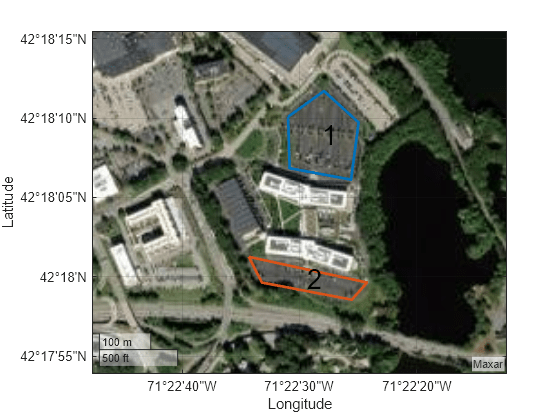
Set the sweep angle for polygons 1 and 2 to 85 and 5 degrees, respectively, to have paths that are parallel to the roads in the parking lots. Then create the coverage planner for that coverage space with the exhaustive solver algorithm.
setCoveragePattern(cs,1,SweepAngle=85)
setCoveragePattern(cs,2,SweepAngle=5)
cp = uavCoveragePlanner(cs,Solver="Exhaustive");
Set the takeoff position to a location in the courtyard, then plan the coverage path.
takeoff = [42.30089 -71.3752, 0];
[wp,soln] = plan(cp,takeoff);
hold on
geoplot(wp(:,1),wp(:,2),LineWidth=1.5);
geoplot(takeoff(1),takeoff(2),MarkerSize=25,Marker=".")
legend("","","Path","Takeoff/Landing")
hold off
This example shows how to plan a coverage path for a region in local coordinates and compares the results of using the exhaustive solver with the results of using the minimum traversal solver.
Define the vertices for a coverage space.
area = [5 8.75; 5 27.5; 17.5 22.5; 25 31.25; 35 31.25; 30 20; 15 6.25];
Because vertices define a concave polygon and the coverage planner requires convex polygons, decompose the polygon into convex polygons. Then create a coverage space with the polygons from decomposition.
polygons = coverageDecomposition(area);
cs = uavCoverageSpace(Polygons=polygons);
Define the takeoff and landing positions at [0 0 0] and [32.25 37.25 0], respectively. Then show the coverage space and plot the takeoff and landing positions.
takeoff = [0 0 0];
landing = [32.25 37.25 0];
show(cs);
exampleHelperPlotTakeoffLandingLegend(takeoff,landing)
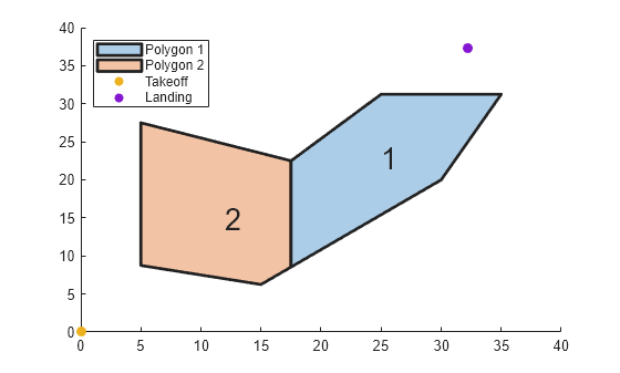
Create a coverage planner with the exhaustive solver algorithm and another coverage planner with a minimum traversal solver algorithm. Because Polygon 2 is closer to the takeoff position, set the visiting sequence of the solver parameters such that we traverse Polygon 2 first.
cpeExh = uavCoveragePlanner(cs,Solver="Exhaustive");
cpMin = uavCoveragePlanner(cs,Solver="MinTraversal");
cpeExh.SolverParameters.VisitingSequence = [2 1];
cpMin.SolverParameters.VisitingSequence = [2 1];
Plan with both solver algorithms using the same takeoff and landing positions.
[wptsExh,solnExh] = plan(cpeExh,takeoff,landing);
[wptsMin,solnMin] = plan(cpMin,takeoff,landing);
Show the planned path for both the exhaustive and the minimum traversal algorithms.
figure
show(cs);
title("Exhaustive Solver Algorithm")
exampleHelperPlotTakeoffLandingLegend(takeoff,landing,wptsExh)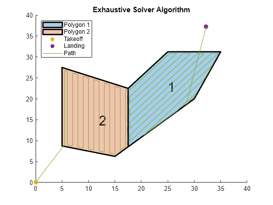
figure
show(cs);
title("Minimum Traversal Solver Algorithm")
exampleHelperPlotTakeoffLandingLegend(takeoff,landing,wptsMin)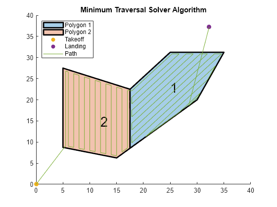
Export the waypoints from the minimum traversal solver to a .waypoints file with the reference frame set to north-east-down.
exportWaypointsPlan(cpMin,solnMin,"coveragepath.waypoints",ReferenceFrame="NED")
Extended Capabilities
Generating code containing the uavCoverageSpace requires you to enable dynamic memory allocation. For more information about enabling dynamic memory allocation, see Set Dynamic Memory Allocation Threshold (MATLAB Coder).
Deploying to embedded real time (ERT) targets is not supported.
Version History
Introduced in R2023auavCoverageSpace now supports code generation with dynamic memory allocation enabled. For more information about enabling dynamic memory allocation, see Set Dynamic Memory Allocation Threshold (MATLAB Coder).
Deploying to embedded real time (ERT) targets is not supported.
MATLAB Command
You clicked a link that corresponds to this MATLAB command:
Run the command by entering it in the MATLAB Command Window. Web browsers do not support MATLAB commands.
Web サイトの選択
Web サイトを選択すると、翻訳されたコンテンツにアクセスし、地域のイベントやサービスを確認できます。現在の位置情報に基づき、次のサイトの選択を推奨します:
また、以下のリストから Web サイトを選択することもできます。
最適なサイトパフォーマンスの取得方法
中国のサイト (中国語または英語) を選択することで、最適なサイトパフォーマンスが得られます。その他の国の MathWorks のサイトは、お客様の地域からのアクセスが最適化されていません。
南北アメリカ
- América Latina (Español)
- Canada (English)
- United States (English)
ヨーロッパ
- Belgium (English)
- Denmark (English)
- Deutschland (Deutsch)
- España (Español)
- Finland (English)
- France (Français)
- Ireland (English)
- Italia (Italiano)
- Luxembourg (English)
- Netherlands (English)
- Norway (English)
- Österreich (Deutsch)
- Portugal (English)
- Sweden (English)
- Switzerland
- United Kingdom (English)