Use C2000 blocks with Multiprocessor Modeling
You can use the C2000™ Microcontroller Blockset blocks with multiprocessor.
Multiprocessor blocks that interact with external hardware (for example ADC or PWM) come in pairs. The pair consists of a data input or output block, such as ADC Read (SoC Blockset), that simulates the behavior of the software drivers and an interface block, such as ADC Interface (SoC Blockset), that simulates the physical behavior of the hardware. During code generation, the data input or output block becomes the driver code for the given hardware peripheral and the interface block gets removed and replaced by the actual device hardware.
C2000 Microcontroller Blockset blocks are equivalent to the data input or output block with the multiprocessor block pairs. In code generation, the blockset generate the appropriate driver code. In simulation, due to the lack of an interface pair, the blocks do not generate any data and can be treated equivalent to the Constant block for input blocks or the Terminator block for output blocks.
Note
You can add a simulation behavior by using Variant Subsystem, Variant Model block.
Add Embedded Coder into Task
To configure an multiprocessor model to use the C2000 Microcontroller Blockset driver blocks, follow these steps.
Create a new multiprocessor model and set the Hardware board parameter to
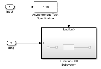
TI F2837D Launchpad.Construct an empty event driven task that is driven by an ADC Interface (SoC Blockset) block. This figure shows the sample model.


In the Simulink® library browser, from the C2000 Microcontroller Blockset > F2837xD group, add the ADC block to the task in the model.

In the ADC block, set the trigger source parameter to
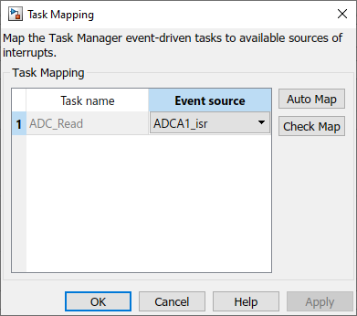
Software.Launch the Hardware Mapping tool. Set the ADC_Task parameter to
ADCA1_isr. This setting maps theADCA1_isrinterrupt to the task containing the ADC block.Use the SoC Builder (SoC Blockset) tool to deploy the model to the connected
TI F2837D
                        Launchpad
. The ADC block can now sample the ADCs from the hardware.
Link Embedded Coder Interrupts to Events
To configure an multiprocessor model to generate interrupts mapped to the C2000 Microcontroller Blockset blocks, follow these steps.
Create a new multiprocessor model and set the Hardware board parameter to
TI F2837D Launchpad.Construct an empty event driven task that is driven by an ADC Interface (SoC Blockset) block. This figure shows the sample model.


In the Simulink library browser, from the C2000 Microcontroller Blockset > F2837xD group, add the ADC block to the task in the model.

In the ADC block, set the trigger source parameter to
Software.Launch the Hardware Mapping tool. Set the ADC_Task parameter to
ADCA1_isr. This maps theADCA1_isrinterrupt to the task containing the ADC block.
Use the SoC Builder (SoC Blockset) tool to deploy the model to the connected
TI F2837D
                        Launchpad
. The ADC blocks can now samples the ADCs from the hardware on the specified interrupt.
This table shows the mapping between the interrupts in the C2000 Microcontroller Blockset blocks and the interrupts in the Hardware Mapping (SoC Blockset) tool.
| Interrupt Type | Block Interrupt Parameter | Task Mapping Interrupt Parameter |
|---|---|---|
| Analog to Digital Converter (ADC) | ADC | ADC |
| Pulse Width Modulator (PWM) | EPWM | EPWM |
EPWM | EPWM | |
| Electrically Evoked Compound Action Potential (ECAP) | ECAP | ECAP |
| Enhanced Quadrature Encoder Pulse (eQEP) | EQEP | EQEP |
| Serial Peripheral Interface (SPI) | SPI | SPI |
SPI | SPI | |
| Direct Memory Address (DMA) | DMA_CH | DMA_CH |
| Inter-Integrated Circuit (I2C) | I2C | I2C |
I2C | I2C | |
| Serial Communication Interface (SCI) | SCI | SCI |
SCI | SCI | |
| Controller Area Network (CAN) | CAN | CAN |
| External Interrupt (XINT) | XINT | XINT |
| Fixed Point Unit (FPU) | FPU_OVERFLOW | FPU_OVERFLOW_isr |
FPU_UNDERFLOW | FPU_UNDERFLOW_isr | |
| Viterbi, Complex Math, and CRC Unit (VCU) | VCU | VCU_isr |
See Also
Timer-Driven Task (SoC Blockset) | Event-Driven Tasks (SoC Blockset) | Hardware Mapping