Main Content

Merge Message Connections for Architectures Using Adapter Block

This example shows how to use an Adapter block to merge multiple message connections in a System Composer™ architecture model.

Open the model.

systemcomposer.openModel('mSysArchMessageMerge');

In this model, message-based communication is constructed between three components: two send components, SAC1 and SAC2, create messages and send them to a receive component, SAC3.

  • The SAC1 component linked to the Simulink® behavior model mBottomupMsg1 generates messages with a value of 1 in every 0.1 interval of sample time..

  • The SAC2 component linked to the Simulink behavior model mBottomupMsg2 generates messages with a value of 8 in every 0.2 interval of sample time.

  • The SAC3 component linked to the Simulink behavior model mBottomupMsg3 receives the merged messages using a rate-based Subsystem block in every 0.5 interval of sample time.

A first-in, first-out (FIFO) queue serves as a message buffer between the components.

The output connections for the SAC1 component and SAC2 component are merged using an Adapter block to the input connection to the SAC3 component.

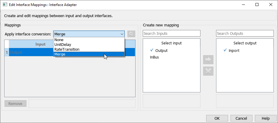
You can double-click the Adapter block to view the Interface Adapter dialog box. Confirm that the interface conversion selection is Merge. Mappings are now disabled.

The Interface Adapter dialog box shows the Apply interface conversion choice Merge.

Simulate the model to merge the messages from the send components SAC1 and SAC2 produced by Simulink behaviors into a single destination, the receive component SAC3.

sim('mSysArchMessageMerge');

Launch the Simulation Data Inspector to view the three messages together on the same diagram.

Simulink.sdi.view

The Simulation Data Inspector shows when messages are sent and received for different components in the architecture model as simulation continues.

See Also

| | |

Related Topics