Main Content

このページの内容は最新ではありません。最新版の英語を参照するには、ここをクリックします。

Stateflow.op.BlockOperatingPoint

Stateflow チャートの操作点情報

説明

Stateflow.op.BlockOperatingPoint オブジェクトには、シミュレーション中の Stateflow® チャートのスナップショットが含まれています。操作点には、以下に関する情報が含まれています。

  • アクティブ ステート

  • チャートの出力データ

  • チャート、ステート、および関数のローカル データ

  • MATLAB® 関数の永続変数と真理値表

作成

変更した操作点の保存の説明にあるように、Simulink® モデルの最終の操作点を保存すると、モデル内の各 Stateflow チャートの Stateflow.op.BlockOperatingPoint オブジェクトを含む Simulink.op.ModelOperatingPoint (Simulink) オブジェクトが作成されます。

関数 get (Simulink) を呼び出し、チャートへのブロック パスを使用して、チャートの Stateflow.op.BlockOperatingPoint オブジェクトにアクセスします。たとえば、モデルの最終の操作点が xFinal で、チャートへのブロック パスが "myModel/Chart" の場合、以下のように入力します。

op = get(xFinal,"myModel/Chart");

プロパティ

Stateflow.op.BlockOperatingPoint オブジェクトには、チャート内のステート、ボックス、関数、ローカル データ、および出力データのそれぞれのプロパティが含まれます。プロパティの名前は、ステート、関数、ボックス、またはデータの名前と一致します。以下に例を示します。

  • チャートに state という名前のステートがある場合、このチャートの Stateflow.op.BlockOperatingPoint オブジェクトには、Stateflow.op.OperatingPointContainer オブジェクトである、state という名前のプロパティがあります。

  • チャートに output という名前のチャート出力がある場合、このチャートの Stateflow.op.BlockOperatingPoint オブジェクトには、Stateflow.op.OperatingPointData オブジェクトである、output という名前のプロパティがあります。

オブジェクト関数

highlightActiveStatesアクティブ ステートの強調表示
removeHighlightingアクティブ ステートの強調表示の解除
cloneStateflow チャートの操作点のコピー
open編集環境でオブジェクトを表示

すべて折りたたむ

  1. sf_aircraft モデルを開きます。

    openExample("stateflow/FaultDetectionControlLogicInAnAircraftControlSystemExample")

    このモデルの詳細については、航空機の昇降舵の制御システムの故障の検出を参照してください。

  2. 最終の操作点を保存するようにモデルを設定します。[コンフィギュレーション パラメーター] ダイアログ ボックスを開き、[データのインポート/エクスポート] ペインで次を行います。

    1. [最終状態] を選択し、操作点の名前を入力します。この例では、xSteadyState を使用します。

    2. [最終の操作点を保存] を選択します。

    3. [OK] をクリックします。

  3. このシミュレーション セグメントの終了時間を設定します。[シミュレーション] タブで、[終了時間]3 に設定します。

  4. シミュレーションを実行します。

  5. Mode Logic チャートの操作点情報を含む Stateflow.op.BlockOperatingPoint オブジェクトにアクセスします。

    blockpath = "sf_aircraft/Mode Logic";
    op = get(xSteadyState,blockpath)
    op = 
    
      Block:    "Mode Logic"    (handle)    (active)
      Path:     sf_aircraft/Mode Logic
    
      Contains:
    
        + Actuators          "State (OR)"                    (active)
        + LI_act             "Function"
        + LO_act             "Function"
        + L_switch           "Function"
        + RI_act             "Function"
        + RO_act             "Function"
        + R_switch           "Function"
          LI_mode            "State output data"		sf_aircraft_ModeType [1,1]
          LO_mode            "State output data"		sf_aircraft_ModeType [1,1]
          RI_mode            "State output data"		sf_aircraft_ModeType [1,1]
          RO_mode            "State output data"		sf_aircraft_ModeType [1,1]
  6. Actuators ステートの操作点情報を含む Stateflow.op.OperatingPointContainer オブジェクトにアクセスします。

    op.Actuators
    ans = 
    
      State:    "Actuators"    (handle)    (active)
      Path:     sf_aircraft/Mode Logic/Actuators
    
      Contains:
    
        + LI            "State (AND)"         (active)
        + LO            "State (AND)"         (active)
        + RI            "State (AND)"         (active)
        + RO            "State (AND)"         (active)
    
  7. チャートの t = 3 でアクティブになっているステートを強調表示します。

    highlightActiveStates(op)

    Stateflow chart showing active states.

  8. 左側の外部アクチュエータの故障を反映するように、ステート LO 内のサブステート アクティビティを変更します。

    setActive(op.Actuators.LO.Isolated)

    Stateflow chart showing active states.

  9. 変更された操作点において、ステート LO 内のサブステート Isolated がアクティブであることを確認します。

    isActive(op.Actuators.LO.Isolated)
    ans =
    
      logical
    
       1

  10. Stateflow エディターでのアクティブ ステートの強調表示を解除します。

    removeHighlighting(op)
  1. モデル old_sf_car を開きます。

    openExample("stateflow/AutomaticTransmissionLegacyExample")
  2. 最終の操作点を保存するようにモデルを設定します。[コンフィギュレーション パラメーター] ダイアログ ボックスを開き、[データのインポート/エクスポート] ペインで次を行います。

    1. [最終状態] を選択し、操作点の名前を入力します。この例では、xSteadyState を使用します。

    2. [最終の操作点を保存] を選択します。

    3. [OK] をクリックします。

  3. このシミュレーション セグメントの終了時間を設定します。[シミュレーション] タブで、[終了時間]10 に設定します。

  4. シミュレーションを実行します。

  5. shift_logic チャートの操作点情報を含む Stateflow.op.BlockOperatingPoint オブジェクトにアクセスします。

    blockpath = "old_sf_car/shift_logic";
    op = get(xSteadyState,blockpath)
    op = 
    
    Block:    "shift_logic"    (handle)    (active)
      Path:     old_sf_car/shift_logic
    
      Contains:
    
        + gear_state         "State (AND)"          (active)
        + selection_state    "State (AND)"          (active)
          gear               "Block output data"    double [1, 1]
          
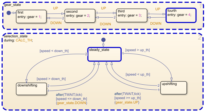
  6. チャートの t = 10 でアクティブになっているステートを強調表示します。

    highlightActiveStates(op)

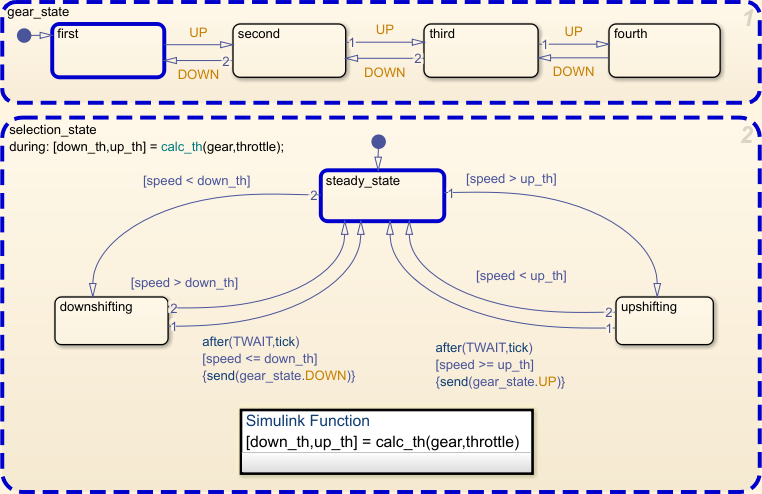
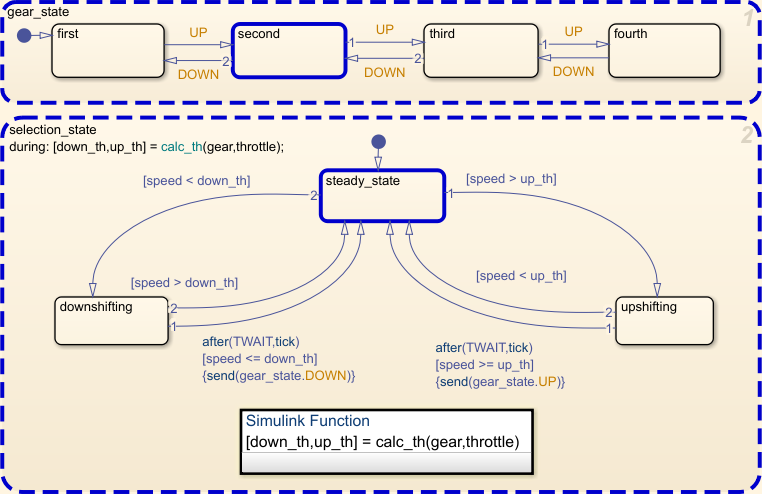
    Stateflow chart showing active states.

  7. チャート出力 gear の操作点情報を含む Stateflow.op.OperatingPointData オブジェクトにアクセスします。

    op.gear
    ans = 
    
          Description: 'Block output data'
             DataType: 'double'
                 Size: '[1, 1]'
                Range: [1x1 struct]
         InitialValue: [1x0 double]
                Value: 4
     
  8. gear の値を 1 に変更します。

    op.gear.Value = 1;
  9. チャート出力 gear の変更された操作点情報を確認します。

    op.gear
    ans = 
    
          Description: 'Block output data'
             DataType: 'double'
                 Size: '[1, 1]'
                Range: [1x1 struct]
         InitialValue: [1x0 double]
                Value: 1
    

バージョン履歴

R2009b で導入

すべて展開する