Model Generic Neutral Connection Using Neutral Port (Three-Phase) Block
This example shows how to use the Neutral Port (Three-Phase) block to model a generic earthing connection in a three-phase network with an unbalanced load. The example also shows the effects of different types of earthing connection on network voltages and highlights when to use the Neutral Port (Three-Phase), Floating Neutral (Three-Phase), or Grounded Neutral (Three-Phase) block.
Model Overview
Open the ee_neutral_three_phase model.
myModel = "ee_neutral_three_phase";
open_system(myModel)
To connect the phases of a three-phase system between blocks in a Simscape™ Electrical™ model, you can use composite or expanded three-phase ports. For more information, see Three-Phase Ports. In this example, you use composite three-phase ports to connect the Voltage Source (Three-Phase), Phase Voltage Sensor (Three-Phase), Load subsystem, and Earthing Variant Subsystem blocks. Composite three-phase ports represent three individual electrical conserving ports with a single block port. You can use composite three-phase ports to build models that correspond to single-line diagrams of three-phase electrical systems. Instead of explicitly connecting each phase of the three-phase system between blocks, you connect all three phases using a single port. You can connect composite three-phase ports only to other composite three-phase ports.
The Voltage Source (Three-Phase) block supplies a peak-to-peak phase voltage of 100 V, which drives a resistive load in the Load subsystem. The Load subsystem contains one Variable Resistor block and two Resistor blocks. Initially, you balance the load with 1 Ohm on each phase. Halfway through the simulation, you increase the A-phase resistance to 5 Ohms. You do not change the resistance of the other two phases during the simulation. You connect the Load subsystem to an earthing connection in the Earthing variant subsystem.
Earthing Variant Subsystem
You can use variant subsystems to include multiple implementations of a model in a separate hierarchy. In this example, you implement the model of each earthing connection as a separate subsystem inside the Earthing variant subsystem and then switch between the subsystems using Variant Controls. For more information, see Variant Subsystem and Introduction to Variant Controls.

To switch between the Generic Neutral, Grounded Neutral, and Floating Neutral subsystems, set the activeVariant workspace variable to "Generic", "Grounded", or "Floating", respectively. The default value of the activeVariant variable is "Generic", which means that the Generic Neutral subsystem is enabled inside the Earthing variant subsystem.
You can connect a composite three-phase port only to another composite three-phase port. This restriction prevents you from connecting the composite three-phase port of the Earthing subsystem to one of the electrical conserving ports of the Resistor block.
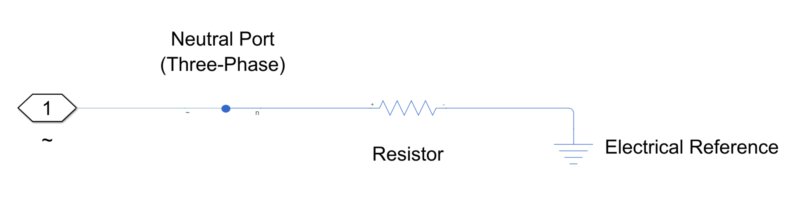
The Neutral Port (Three-Phase) block creates a neutral point in the three-phase system which connects the phases to an electrical conserving port. It has one three-phase port and one single-phase port. To connect the Resistor block to the three-phase network, connect the single-phase port of the Neutral Port (Three-Phase) block to one of the single-phase ports of the Resistor block. By connecting a Neutral Port (Three-Phase) block, a Resistor block, and an Electrical Reference block to the network, you can model a neutral connection with a specified resistance.
The Earthing variant subsystem contains another two subsystems. The Floating Neutral subsystem connects the input to a Floating Neutral (Three-Phase) block. The Grounded Neutral subsystem connects the input to a Grounded Neutral (Three-Phase) block.
Model Grounded Neutral Connection
To create and connect a neutral point to the ground, use the Grounded Neutral (Three-Phase) block. In this model, connecting a neutral point to the ground is equivalent to setting the Resistance parameter of the Resistor block in the Generic Neutral subsystem to 0.
Model a grounded neutral earthing connection with the Generic Neutral subsystem. Set the Resistance parameter of the Resistor block to 0.
set_param(myModel+"/Earthing/Generic Neutral/Resistor","R","0");
Simulate the model.
sim(myModel)

Calculate the current through the Resistor block in the Generic Neutral subsystem.
i_generic_0 = simlog_ee_neutral_three_phase.Earthing.Generic_Neutral.Resistor.i.series.values("A");
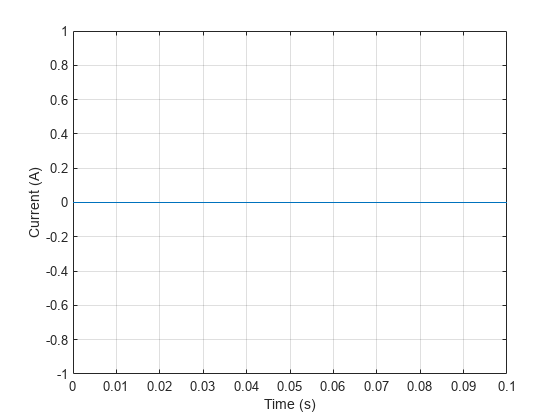
t_generic_0 = simlog_ee_neutral_three_phase.Earthing.Generic_Neutral.Resistor.i.series.time;Plot the evolution of current over time. When the load is balanced, no current travels through the neutral point. When the load becomes unbalanced, the neutral conductor carries some current back to the supply.
plot(t_generic_0,i_generic_0)
xlabel("Time (s)")
ylabel("Current (A)")
grid on

Calculate the voltage across the Load subsystem.
v_load = simlog_ee_neutral_three_phase.Phase_Voltage_Sensor_Three_Phase.V_output.series.values("V");
t_load = simlog_ee_neutral_three_phase.Phase_Voltage_Sensor_Three_Phase.V_output.series.time;
Model the grounded neutral earthing connection with the Grounded Neutral (Three-Phase) block in the Grounded Neutral subsystem. Change the active subsystem to the Grounded Neutral subsystem.
activeVariant = "Grounded";Simulate the model again.
sim(myModel);
Calculate the voltage across the Load subsystem again.
v_load_grounded = simlog_ee_neutral_three_phase.Phase_Voltage_Sensor_Three_Phase.V_output.series.values("V");
t_load_grounded = simlog_ee_neutral_three_phase.Phase_Voltage_Sensor_Three_Phase.V_output.series.time;
Plot the results from both simulations. Because the load is connected to the ground, the phase voltage with a grounded neutral connection remains unaffected throughout the simulation.
As expected, the simulation results agree when the Generic Neutral subsystem or Grounded Neutral subsystem is active. You do not need the Neutral-Port (Three-Phase) block when you set the Resistance parameter of the Resistor block in the Generic Neutral subsystem to 0. You can use the Grounded Neutral (Three-Phase) block to connect the neutral point to the ground instead. In general, if you want to create a neutral point that is connected to the ground, use the Grounded Neutral (Three-Phase) block.
plot(t_load,v_load,"-")
xlabel("Time (s)")
ylabel("Voltage (V)")
ylim([-150 150])
grid on
hold on
plot(t_load_grounded,v_load_grounded,"--")
legend("A generic","B generic","C generic","A grounded","B grounded","C grounded","Location","eastoutside")
hold off
Model Floating Neutral Connection
To create a floating neutral point, use a Floating Neutral (Three-Phase) block. For example, you can use the Floating Neutral (Three-Phase) block to model a broken or disconnected neutral wire. You can also model a broken or disconnected neutral wire by setting the Resistance parameter of the Resistor block in the Generic Neutral Subsystem to Inf.
Model a floating neutral earthing connection with the Generic Neutral subsystem. Change the active subsystem to the Generic Neutral subsystem for the simulation by setting activeVariant to "Generic" and set the Resistance parameter of the Resistor block to Inf.
activeVariant = "Generic";
set_param(myModel+"/Earthing/Generic Neutral/Resistor","R","Inf");
Simulate the model.
sim(myModel);
Calculate the current through the Resistor block in the Generic Neutral subsystem.
i_generic_inf = simlog_ee_neutral_three_phase.Earthing.Generic_Neutral.Resistor.i.series.values("A");
t_generic_inf = simlog_ee_neutral_three_phase.Earthing.Generic_Neutral.Resistor.i.series.time;
Plot the evolution of current over time. If the neutral wire is broken or disconnected, the unbalanced current cannot return to the supply via the neutral conductor. This current takes the path back to the supply through the lines.
plot(t_generic_inf,i_generic_inf)
xlabel("Time (s)")
ylabel("Current (A)")
grid on

Calculate the voltage across the Load subsystem.
v_load = simlog_ee_neutral_three_phase.Phase_Voltage_Sensor_Three_Phase.V_output.series.values("V");
t_load = simlog_ee_neutral_three_phase.Phase_Voltage_Sensor_Three_Phase.V_output.series.time;
Model the floating neutral earthing connection with the Floating Neutral (Three-Phase) block in the Floating Neutral subsystem. Set the activeVariant workspace variable to "Floating" and simulate the model again.
activeVariant = "Floating";
sim(myModel);
Calculate the voltage across the Load subsystem again.
v_load_floating = simlog_ee_neutral_three_phase.Phase_Voltage_Sensor_Three_Phase.V_output.series.values("V");
t_load_floating = simlog_ee_neutral_three_phase.Phase_Voltage_Sensor_Three_Phase.V_output.series.time;
Plot the results of both simulations. In the floating neutral scenario, the phase voltage changes significantly as the load becomes unbalanced, according to the different resistance values in each phase. In this case, if a system operator monitors only line voltages, undesirable overvoltages can occur on individual phases without being observed. Overvoltages often cause overheating, accelerated breakdown of insulation, or other system problems.
As expected, the simulation results agree when the Generic Neutral subsystem or Floating Neutral subsystem is active. You do not need the Neutral Port (Three-Phase) block when you set the Resistance parameter of the Resistor block in the Generic Neutral subsystem to Inf. You can use the Floating Neutral (Three-Phase) block to connect the individual phases of a three-phase system to form a floating neutral point instead. In general, if you do not need to connect the Neutral Port (Three-Phase) block to other blocks with a single-phase port, use a Floating Neutral (Three-Phase) block.
plot(t_load,v_load,"-")
xlabel("Time (s)")
ylabel("Voltage (V)")
grid on
hold on
plot(t_load_floating,v_load_floating,"--")
legend("A generic","B generic","C generic","A floating","B floating","C floating","Location","eastoutside")
hold off

Model Generic Neutral Connection
You can use the Neutral Port (Three-Phase) block to create a neutral point to which you can connect a composite three-phase port and an electrical conserving port. In this example, you connect the neutral point to the Resistor block in the Generic Neutral Subsystem to model a neutral connection with a nonzero and finite resistance. You cannot model this scenario with the Generic Neutral (Three-Phase) or Floating Neutral (Three-Phase) blocks.
Model a generic neutral earthing connection with the Generic Neutral subsystem. To change the active subsystem to the Generic Neutral subsystem for the simulation, set activeVariant to "Generic" and set the Resistance parameter of the Resistor block to 1.
activeVariant = "Generic";
set_param(myModel+"/Earthing/Generic Neutral/Resistor","R","1");
Simulate the model.
sim(myModel);

Calculate the current through the resistor in the Generic Neutral subsystem.
i_generic_1 = simlog_ee_neutral_three_phase.Earthing.Generic_Neutral.Resistor.i.series.values("A");
t_generic_1 = simlog_ee_neutral_three_phase.Earthing.Generic_Neutral.Resistor.i.series.time;
Plot the evolution of current over time, including the results from previous simulations. For a generic neutral earthing connection, when the Resistance parameter of the Resistor block is finite, only a portion of the unbalanced current returns to the supply via the neutral conductor.
plot(t_generic_0,i_generic_0,"-")
xlabel("Time (s)")
ylabel("Current (A)")
grid on
hold on
plot(t_generic_1,i_generic_1,"-")
plot(t_generic_inf,i_generic_inf,"-")
legend("0 Ohms","1 Ohm","inf Ohms","Location","northwest")
hold off

Calculate the phase voltage across the Load subsystem.
v_load = simlog_ee_neutral_three_phase.Phase_Voltage_Sensor_Three_Phase.V_output.series.values("V");
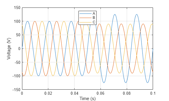
t_load = simlog_ee_neutral_three_phase.Phase_Voltage_Sensor_Three_Phase.V_output.series.time;Plot the evolution of voltage over time. As with the floating neutral scenario, the phase voltage changes significantly as the load becomes unbalanced. However, the peak values decrease from 136 V to 125 V across the A-phase and from 90 V to 87 V across the B-phase and C-phase.
plot(t_load,v_load)
xlabel("Time (s)")
ylabel("Voltage (V)")
grid on
legend("A","B","C","Location","north")
See Also
Neutral Port (Three-Phase) | Grounded Neutral (Three-Phase) | Floating Neutral (Three-Phase)