Fault Detection of Electric Vehicle Charger
This example analyzes the fault of an electric vehicle (EV) charger using Simscape™ Electrical™ to model the grid, the converter, and its control unit. The reliability of these chargers is an important factor in their adoption. In this example, you use measurements from the grid and the DC side of the converter to detect a gate driver fault in the converter. To analyze and detect a fault, first you generate synthetic data for different conditions with and without faults. Then you use this data to train a classification algorithm using the Classification Learner (Statistics and Machine Learning Toolbox). Finally, you use the trained model to identify or detect faults in any phase and to generate the code for deployment on hardware. You can extend this model for other system level variations or noises by having a much larger and comprehensive training dataset.
Open EV Charger Model
Open the ee_EVchargerFaultAnalysis model.
open_system("ee_EVchargerFaultAnalysis.slx")
The model comprises three major subsystems: Grid, Converter, and ControlUnit. The resistor block, Load, represents the system load. In this example, you simulate the fault of gate drivers for one or more IGBT duty cycles. No other fault is considered. The gateDriveFault block defines a fault in the gate driver operation. The input to the Converter subsystem is a column vector of six elements, which represent the six IGBTs. Each element is either 0 (no fault) or 1 (fault). You can simulate uncertainties in system by setting the Resistance parameter of the Load block to different values. The ee_EVchargerFaultAnalysis_data MAT file stores the measured total harmonic distortion (THD) on the AC grid side.
The Grid subsystem is modeled as an ideal voltage source. To model a grid with a different grid voltage and frequency, change the parameters in the ee_EVchargerFaultAnalysis_ini file.
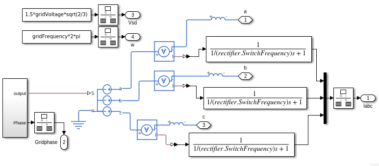
The Converter subsystem is modeled as a three-phase, two-level converter using IGBT (Ideal, Switching) blocks. You can fault any of the six IGBTs by changing the duty cycle, D, to zero. To change the duty cycle, use the gateDriveFault parameter.

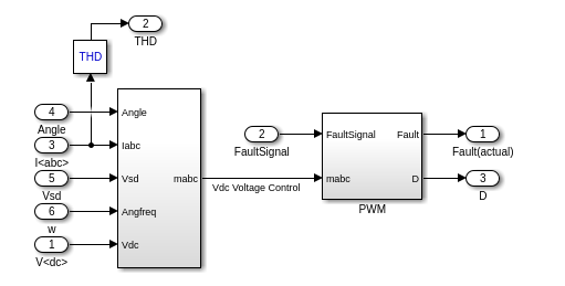
The ControlUnit subsystem controls the three-phase converter by using id-iq control, with unity power-factor operation, that enables a constant DC voltage of 800V.
In this example, you programmatically simulate multiple instances of fault behavior. The grid-side THD and the Load resistance values are used for training classification of faults. The classification aims to identify the gate driver on the faulted phases (a, b, c, or one of their combinations). To collect enough data to train the model, you run multiple simulations for different load conditions and generate synthetic data for fault and no fault scenarios.
Generate Training Data
Define operating conditions, such as the grid voltage and the system load variation, for the simulation.
% Grid data
gridVoltOptions = 415;         % V,   Line-Line rms voltage
loadOptions = [8 9 10 11 12];  % Ohm, System load
To run simulations for all grid and load options and create the training data for the Classification Learner, at the MATLAB® Command Window, enter ee_EVchargerFaultAnalysis_training to open the script.
This function generates the training data for fault and no fault scenarios. To generate the training data, the total harmonic distortion values from each simulation are averaged over a time period of [tStart, tEnd].
Train and Validate Model
This example uses the MATLAB Classification Learner App to identify and train a classification learning algorithm for the system. For more information, see Train Classification Models in Classification Learner App (Statistics and Machine Learning Toolbox). First, load the training data in your workspace. The ee_EVchargerFaultAnalysis_trainingData MAT file already stores the pre-generated training data. The training labels denote faulted or unfaulted status (1 or 0) of the gate drives corresponding to the a, b, and c phases of the AC grid. It is denoted using a three-digit number, where the leftmost digit represents the a-phase of the gate driver, middle digit represents the b-phase of the gate driver, and the rightmost digit represents the c-phase of the gate driver. Each digit can be 0 or 1. Only one gate driver or a combination of two gate drivers might fault.
trainingData=load("ee_EVchargerFaultAnalysis_trainingData.mat").trainingData;
trainingData.gridDCvolt = [];
trainingData.driverFault = categorical(trainingData.driverFault);
trainingData.driverFault = categorical(trainingData.driverFault,...
    ["0","1","10","11","100","101","110"],"Ordinal",true);
The first 4 columns in trainingData represent the data for training and the fifth column denotes the labels marked against each set of data point.
Load trainingData workspace parameter in the Classification Learner App and train all available models on the data. The Ensemble Bagged Trees is the best trained model with an accuracy of over 90%.
Export the trained model from the App and save it in a ee_EVchargerFaultAnalysis_trainClassifier.m file. To obtain the trained classifier, at the MATLAB Command Window, enter:
[trainedClassifier, validationAccuracy] = ...
    ee_EVchargerFaultAnalysis_trainClassifier(trainingData)
trainedClassifier = struct with fields:
predictFcn: @(x)ensemblePredictFcn(predictorExtractionFcn(x))
RequiredVariables: {'gridTHD_a' 'gridTHD_b' 'gridTHD_c' 'systemLoad'}
ClassificationEnsemble: [1×1 classreg.learning.classif.ClassificationBaggedEnsemble]
About: 'This struct is a trained model exported from Classification Learner R2022a.'
HowToPredict: 'To make predictions on a new table, T, use: ↵ yfit = c.predictFcn(T) ↵replacing 'c' with the name of the variable that is this struct, e.g. 'trainedModel'. ↵ ↵The table, T, must contain the variables returned by: ↵ c.RequiredVariables ↵Variable formats (e.g. matrix/vector, datatype) must match the original training data. ↵Additional variables are ignored. ↵ ↵For more information, see How to predict using an exported model.'
validationAccuracy =
0.9081
Verify Model Predictions
To verify the model trained using the Classification Learner on an entirely new dataset, at the MATLAB Command Window, enter ee_EVchargerFaultAnalysis_verify to open the script.
The ee_EVchargerFaultAnalysis_testData MAT file contains pre-generated test data for this example. To verify the accuracy of the trained model, load the test data and run these commands.
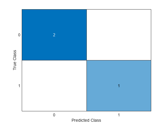
testData=load("ee_EVchargerFaultAnalysis_testData.mat").testData;
testData.gridDCvolt = [];
testData.driverFault = categorical(testData.driverFault);
testData.driverFault = categorical(testData.driverFault,...
    ["0","1","10","11","100","101","110"],"Ordinal",true);
% Predicted labels
pred_fault = trainedClassifier.predictFcn(testData(:,1:4));
% Actual labels
real_fault = testData(:,5);
confusionchart(pred_fault,table2array(real_fault))

The Predicted Class and the True Class match for all the test data points. This shows a very good success rate in identifying the right kind of fault or no fault.
Generate and Deploy Code
To deploy the trainedClassifier model trained with the Classification Learner App, run these steps.
saveLearnerForCoder(trainedClassifier.ClassificationEnsemble,...
    "ee_EVchargerFaultAnalysis_codegen");
To simulate for a different system load and create a codegen model, run these commands.
% Simulation parameters
systemLoadR=11.2;
gridVoltage=415;
gateDriveFault=[1;0;0;0;0;0]; % Gate Driver for AH faulted (a phase)
realFault_a=min(1,gateDriveFault(1,1)+gateDriveFault(2,1));
realFault_b=min(1,gateDriveFault(3,1)+gateDriveFault(4,1));
realFault_c=min(1,gateDriveFault(5,1)+gateDriveFault(6,1));
%
% Check fault during time sample of 0.25 (= tEnd-tStart) seconds
tStart = 0.2;
tEnd = 0.45;
Run the ee_EVchargerFaultAnalysis SLX file to save the data in the ee_EVchargerFaultAnalysis_data MAT file. Use the measured data (THD, system load) to detect if there was one or more faults in the gate drivers.
thd=load("ee_EVchargerFaultAnalysis_data.mat");
startData=find(thd.THD.Time==tStart);
endData=find(thd.THD.Time==tEnd);
The ee_EVchargerFaultAnalysis_codegenFunc function calls the ee_EVchargerFaultAnalysis_codegen MAT file that stores the trained classification suited for code generation.
gridTHD_a=thd.THD.Data(startData:endData,1);
gridTHD_b=thd.THD.Data(startData:endData,2);
gridTHD_c=thd.THD.Data(startData:endData,3);
lenData=length(gridTHD_a);
sysLoad=ones(lenData,1)*systemLoadR;
% Measured Data
measData=[sysLoad,gridTHD_a,gridTHD_b,gridTHD_c];
% Predict if there is any fault detected
[predFault_a,predFault_b,predFault_c] = ...
    ee_EVchargerFaultAnalysis_codegenFunc(measData);
%
if isequal(predFault_a,realFault_a) && ...
        isequal(predFault_b,realFault_b) && ...
        isequal(predFault_c,realFault_c)
    disp('*** Prediction : Correct !!')

else
    disp('*** Prediction : Incorrect !!')
end
*** Prediction : Correct !!
confusionchart(...
    [predFault_a,predFault_b,predFault_c],...
    [realFault_a,realFault_b,realFault_c]);
The ee_EVchargerFaultAnalysis_codegenFunc function is now ready for code generation. For more information, see Generate Code at Command Line Using Model Exported from Machine Learning App (Statistics and Machine Learning Toolbox).
See Also
IGBT (Ideal, Switching) | Diode | Classification Learner (Statistics and Machine Learning Toolbox)
Topics
- Classify Motor Faults Using Deep Learning (Deep Learning Toolbox)
- Model Short-Circuit Fault in EV Charging Cable
- Battery Pack DC Fast Charging
- DC Fast Charger for Electric Vehicle
- On-Board Charger for Two-Wheeler Electric Vehicle
- Train Classification Models in Classification Learner App (Statistics and Machine Learning Toolbox)