generateMotorDriveROM
Syntax
Description
The generateMotorDriveROM function takes a motor drive
subsystem and creates a reduced-order model (ROM) in the form of a Motor &
Drive (System Level) block and parameterizes it with tabulated maximum
torque in function of rotor speed and DC voltage, and tabulated power dissipated in function
of rotor speed, shaft torque, and DC voltage.
The model-order reduction transforms a high-fidelity, computationally expensive model into an equivalent model that is easier to interpret and runs faster. This model is called a reduced-order model. A ROM captures the steady-state behavior of a motor drive in terms of energy balance and maximum torque capability. A ROM can also accurately capture the first-order response to changes in torque demand.
You can use the ROM to run faster simulations, by replacing the original motor drive subsystem with the generated ROM subsystem. ROMs enable you to quickly test and analyze system-level scenarios where the motor drive interacts with other systems.
generateMotorDriveROM( generates an
equivalent energy-based model from the electric motor drive subsystem
sys)sys.
generateMotorDriveROM(
specifies options using one or more name-value arguments in addition to the input argument
in previous syntaxes. For example, for a nominal DC supply voltage equal to 500 V, set
sys,Name=Value)NominalDCVoltage to 500.
ROMParameters = generateMotorDriveROM(sys,Name=Value)
Examples
This example shows how to generate the reduced order model (ROM) of a PMSM motor drive subsystem.
Open Model
Open the PMSMMotorDrive.slx model.
open_system("PMSMMotorDrive")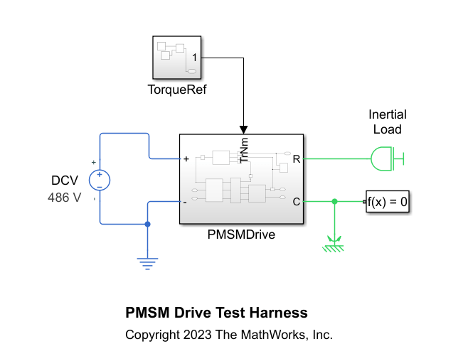
The PMSMDrive subsystem comprises a detailed motor drive model with a converter, a motor, sensors, and a torque control loop. This motor drive has a nominal DC voltage of 486 V, a maximum shaft speed of 4000 RPM, and a rated torque of 90 Nm.

Ensure that the subsystem has the correct port names and port types. The subsystem must follow these rules:
The ports of the subsystem must match the ports of the Motor & Drive (System Level) block: +, -, R, C, and a Simulink input port for the torque reference, in Nm.
The subsystem must be able to follow the torque reference dynamically for all torque values below the maximum torque you designed the drive for.
The initial state must be such that the torque is zero.
Generate ROM
Run the generateMotorDriveROM function to generate the ROM of the PMSMDrive subsystem and set these options:
The drive operates as a motor (positive speed, positive torque).
Based on the motor drive specifications, the nominal DC voltage is 486 V, the maximum speed is 4000 rpm, and the nominal torque is 90 Nm.
For a good balance between ROM accuracy and computational cost to generate the ROM, choose a grid of 12 speed breakpoints, 40 torque breakpoints, and three DC voltage breakpoints. Set the DC voltage breakpoints to 80%, 90%, and 100% of the nominal voltage. If you require more accuracy, reduce the ROM interpolation error by increasing the number of breakpoints to specify a grid with higher resolution. However, a higher number of breakpoints increases the computational cost to generate the ROM.
To run simulations in parallel, if a parallel pool is available or if MATLAB® can automatically create one, set
UseParallelto"auto".
generateMotorDriveROM("PMSMMotorDrive/PMSMDrive", ...
    OperatingMode="motor", ...
    NominalDCVoltage=486, ...
    MaxRotorRPM=4000, ...
    NominalTorque=90, ...
    NumRPMBreakpoints=12, ...
    NumTorqueBreakpoints=40, ...
    PerUnitDCVoltageBreakpoints=[0.8, 0.9, 1.0], ...
    UseParallel="auto");
Starting parallel pool (parpool) using the 'Processes' profile ...
15-May-2025 17:06:36: Job Queued. Waiting for parallel pool job with ID 1 to start ...
15-May-2025 17:07:37: Job Running. Waiting for parallel pool workers to connect ...
Connected to parallel pool with 4 workers.
Using:
  NominalDCVoltage = 486
  MaxRotorRPM = 4000
  NominalTorque = 90
Auto-selected nominal operating conditions:
  DCV = 486
  RPM = 400
  TrNm = 90
Validating harness initialization at nominal operating conditions ...
Harness initialization validated successfully.
Calculating torque time constant at nominal operating conditions ...
	Running iteration #1 : StopTime = 0.01
	Running iteration #2 : StopTime = 0.03
	Running iteration #3 : StopTime = 0.06
	Running iteration #4 : StopTime = 0.12
Estimated torque time constant = 0.0017344 seconds.
![Figure contains an axes object. The axes object with title Simulation Results for Torque Time Constant Calculation DCV = 486 RPM = 400, xlabel Time [s], ylabel Torque [N*m] contains 3 objects of type line. These objects represent reference, response, fitted response (ROM).](../../examples/simscapeelectrical/win64/GenerateROMOfMotorDriveSubsysExample_03.png)
Finding maximum torque at zero speed ...
	Running iteration #1 : StopTime = 0.036016, MaxTrqNmSearch = 180
	Running iteration #2 : StopTime = 0.036016, MaxTrqNmSearch = 360
Found an acceptable torque search range = 540 N*m.
Running simulations with constant speed and voltage, and ramp in reference torque ...
  RPMBkpts = [0 363.636363636364 727.272727272727 1090.90909090909 1454.54545454545 1818.18181818182 2181.81818181818 2545.45454545455 2909.09090909091 3272.72727272727 3636.36363636364 4000]
  DCVBkpts = [388.8;437.4;486]
Each simulation ramps the reference torque from 0 to 540 N*m.
[15-May-2025 17:11:48] Checking for availability of parallel pool...
[15-May-2025 17:11:53] Starting Simulink on parallel workers...
[15-May-2025 17:14:31] Configuring simulation cache folder on parallel workers...
[15-May-2025 17:14:36] Loading model on parallel workers...
[15-May-2025 17:15:37] Running simulations...
[15-May-2025 17:24:40] Cleaning up parallel workers...
Validation scenario: step + ramp torque reference.

Running original and ROM simulations in validation scenario ...
	Original system compile-time in validation scenario: 32.175 seconds.
	ROM system compile-time in validation scenario: 18.7306 seconds.
	Compile-time speedup factor in validation scenario: x1.7178.

	Original system run-time in validation scenario: 30.8043 seconds.
	ROM system run-time in validation scenario: 0.89913 seconds.
	Run-time speedup factor in validation scenario: x34.2601.

Calculating power loss summary to compare original and ROM in validation scenario ...
	Original sys power loss summary:
                                        LoggingNode                                        Power
    ___________________________________________________________________________________    ______

    "PMSMDrive.PMSM"                                                                       952.25
    "PMSMDrive.Three_Phase_Inverter.Average_Value_Voltage_Source_Converter_Three_Phase"    314.29

	ROM power loss summary:
                  LoggingNode                   Power
    ________________________________________    _____

    "MotorDriveROM.Motor_Drive_System_Level"    1258


Generating plot to compare original and ROM in validation scenario ...
![Figure contains 3 axes objects. Axes object 1 with title Original and ROM simulation results for: DCV = 486 RPM ramp from 0 to 400, xlabel time [s], ylabel Electrical torque [N*m] contains 3 objects of type line. These objects represent reference, original, ROM. Axes object 2 with xlabel time [s], ylabel DC supply current [A] contains 2 objects of type line. These objects represent original, ROM. Axes object 3 with xlabel time [s], ylabel Rotor RPM contains 2 objects of type line. These objects represent original, ROM.](../../examples/simscapeelectrical/win64/GenerateROMOfMotorDriveSubsysExample_05.png)
ROM generation complete.
Input Arguments
Name-Value Arguments
Output Arguments
Limitations
The generated ROM does not include high-order dynamics, including torque ripple and vibrations, or power switching dynamics. If your model must represent these high-order dynamic behaviors, do not replace the original system.
Algorithms
The generateMotorDriveROM function runs simulations to calculate the
parameters that define the motor drive system ROM. The function follows these steps:
Compute the torque-tracking time constant — The function simulates a step response from 0 Nm to the nominal torque value specified by the
NominalTorqueargument and at the nominal DC supply voltage, specified in theNominalDCVoltagewhile keeping the rotor speed constant at 10% of the maximum speed. The function fits the response to a first-order response to compute the torque-tracking time constant.Find the maximum torque at zero speed — The function simulates a ramp reference torque response with increasingly higher slopes until the motor drive is unable to keep up with the demand and detaches from the reference. The function uses the value of the
NominalTorqueargument as a first guess for this iterative search algorithm. This maximum torque value determines the torque breakpoints for the power losses lookup table.Compute maximum torque-speed envelopes and power losses at the table lookup breakpoints — The function runs a simulation for each speed and voltage breakpoint. The simulation consists of a ramp reference torque response with a slowly increasing torque reference from 0 Nm to the maximum torque value.