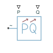
Dynamic Load (Three-Phase)
Balanced three-phase dynamic load
Libraries:
Simscape /
Electrical /
Passive
Description
The Dynamic Load (Three-Phase) block models a balanced dynamic load for a balanced three-phase supply.
This table shows how the block calculates the consumed active and reactive power based on the voltage from the supply, V.
| Range of V Values | Consumed Active and Reactive Power |
|---|---|
The block models a load with an impedance equal to: |
In these equations:
Vmin is the value of the Minimum supply voltage (phase-to-phase RMS) parameter.
Pactual is the consumed active power of the Dynamic Load (Three-Phase) block.
Pin is the input active power of the Dynamic Load (Three-Phase) block, determined by external input port P.
Qactual is the consumed reactive power of the Dynamic Load (Three-Phase) block.
Qin is the input reactive power of the Dynamic Load (Three-Phase) block, determined by external input port Q.
The Dynamic Load (Three-Phase) block consumes or generates active power depending on the polarity of input active power Pin. If Pin > 0, the block consumes active power. If Pin < 0, the block generates active power.
Faults
To model a fault in the Dynamic Load (Three-Phase) block, in the Faults section, click Add fault next to the fault that you want to model. For more information about fault modeling, see Fault Behavior Modeling and Fault Triggering.
The Dynamic Load (Three-Phase) block allows you to model an electrical fault as an open circuit. The block can trigger fault events at a specific time.
Load-Flow Analysis
If the block is in a network that is compatible with the frequency-time simulation mode, you can perform a load-flow analysis on the network. A load-flow analysis provides steady-state values that you can use to initialize a machine.
For more information, see Perform a Load-Flow Analysis Using Simscape Electrical and Frequency and Time Simulation Mode.