Best-Form Mathematical Models
Series RLC Example
You can often formulate the mathematical system you are modeling in several ways. Choosing the best-form mathematical model allows the simulation to execute faster and more accurately. For example, consider a simple series RLC circuit.
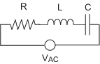
According to Kirchoff's voltage law, the voltage drop across this circuit is equal to the sum of the voltage drop across each element of the circuit.
Using Ohm's law to solve for the voltage across each element of the circuit, the equation for this circuit can be written as
You can model this system in Simulink® by solving for either the resistor voltage or inductor voltage. Which you choose to solve for affects the structure of the model and its performance.
Solving Series RLC Using Resistor Voltage
Solving the RLC circuit for the resistor voltage yields
Circuit Model
The following diagram shows this equation modeled in Simulink where R is 70,
C is 0.00003, and L is
0.04. The resistor voltage is the sum of the voltage source, the
capacitor voltage, and the inductor voltage. You need the current in the circuit to
calculate the capacitor and inductor voltages. To calculate the current, multiply the
resistor voltage by a gain of 1/R. Calculate the capacitor voltage by
integrating the current and multiplying by a gain of 1/C. Calculate
the inductor voltage by taking the derivative of the current and multiplying by a gain of
L.
This formulation contains a Derivative block associated with the inductor. Whenever possible, you should avoid mathematical formulations that require Derivative blocks as they introduce discontinuities into your system. Numerical integration is used to solve the model dynamics though time. These integration solvers take small steps through time to satisfy an accuracy constraint on the solution. If the discontinuity introduced by the Derivative block is too large, it is not possible for the solver to step across it.
In addition, in this model the Derivative, Sum, and two Gain blocks create an algebraic loop. Algebraic loops slow down the model's execution and can produce less accurate simulation results. See Algebraic Loop Concepts for more information.
Solving Series RLC Using Inductor Voltage
To avoid using a Derivative block, formulate the equation to solve for the inductor voltage.
Circuit Model
The following diagram shows this equation modeled in Simulink. The inductor voltage is the sum of the voltage source, the resistor voltage, and the capacitor voltage. You need the current in the circuit to calculate the resistor and capacitor voltages. To calculate the current, integrate the inductor voltage and divide by L. Calculate the capacitor voltage by integrating the current and dividing by C. Calculate the resistor voltage by multiplying the current by a gain of R.
This model contains only integrator blocks and no algebraic loops. As a result, the model simulates faster and more accurately.