このページの内容は最新ではありません。最新版の英語を参照するには、ここをクリックします。
Control Data Transfer Behavior in Generated Code
How you control data transfer behavior in generated code depends on whether you are working with a single-rate or multirate model. For single-rate models, use the Simulink® Concurrent Execution tool. To enable that tool, select the solver model configuration parameter Allow tasks to execute concurrently on target.
Control data transfer behavior in code generated from multirate models by configuring Rate Transition blocks that you insert manually or that Simulink inserts automatically between blocks that represent callable functions.
This table compares the two approaches.
| Benefit | Automatic Insertion | Manual Insertion |
|---|---|---|
| Convenience | X | |
| Control over data transfer tradeoffs regarding data integrity, determinism, latency, memory usage | X | |
| Blocks do not clutter model canvas | X | |
| Block visible in model canvas | X |
When inserted between two such blocks that have different sample rates, the Rate Transition block automatically detects the type of transition and configures its input and output sample rates for that type of transition. The critical decision that you can make when you insert a Rate Transition block manually is the choice of data transfer behavior to configure for handling the different rates during real-time code execution. Base your choice of behavior on considerations of:
Safety
Memory usage
Performance
Insert Rate Transition Blocks Automatically
To instruct the Simulink engine to insert Rate Transition blocks into a multirate model for you, select model configuration parameter Automatically handle rate transition for data transfer. When you select this parameter:
Simulink inserts hidden Rate Transition blocks in the block diagram.
Simulink handles transitions between tasks for blocks that are configured to use periodic and asynchronous sample times.
The code generator produces code for Rate Transition blocks that Simulink automatically inserts. The code is identical to the code generated for Rate Transition blocks that you can insert manually.
Automatically inserted Rate Transition blocks maintain data integrity for periodic and asynchronous tasks. You cannot alter this behavior.
The level of determinism that automatically inserted Rate Transition blocks provide differs between periodic and asynchronous tasks. For periodic tasks, the blocks operate with the level of determinism specified by model configuration parameter Deterministic data transfer. The default setting is
Whenever possible, which enables determinism for data transfers between callable functions that have periodic sample times that are related by an integer multiple. For asynchronous tasks, the Simulink engine does not configure the blocks for determinism. For more information, see Deterministic data transfer. For finer-level control over data transfer behavior, insert and configure Rate Transition blocks manually (see Insert and Configure Rate Transition Blocks Manually (Embedded Coder)).
For example, in this model, SineWave2 has a sample time of 2 seconds, and SineWave3 has a sample time of 3 seconds.
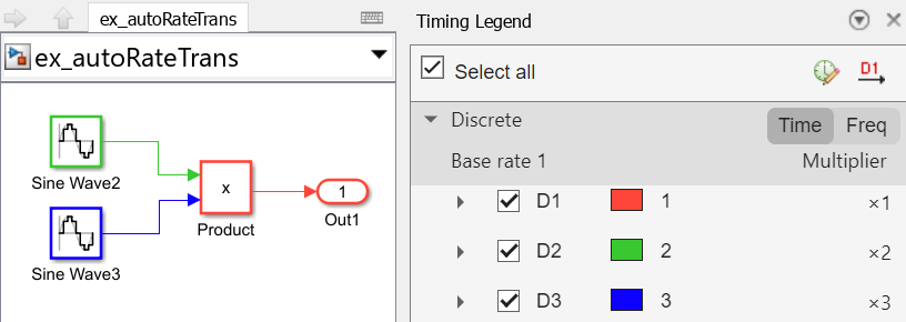
When you select model configuration parameter Automatically handle rate transition for data transfer, as done for this model, Simulink inserts a Rate Transition block between each Sine Wave block and the Product block. The inserted blocks have parameter settings that reconcile with the Sine Wave block sample times.
If the input port and output port data sample rates in a model are not multiples of each other, Simulink inserts a Rate Transition block that has a sample rate that is the greatest common divisor (GCD) of the two rates. If another block in the model contains this new rate, an error occurs during simulation. In this case, insert a Rate Transition block manually.
Control Default Level of Determinism for Automatically Inserted Rate Transition Blocks
Control the default level of determinism for automatically inserted Rate Transition blocks by using the model configuration parameter Deterministic data transfer. This parameter applies to rate transitions between periodic tasks. The Rate Transition block cannot provide determinism for asynchronous rate transitions. The Deterministic data transfer parameter:
Controls whether and under what conditions Simulink selects the Rate Transition block parameter Ensure deterministic data transfer (maximum delay).
Is not enabled by default. How you enable the parameter depends on the setting of the solver parameter Type. For details, see Deterministic data transfer.
This table lists data transfer behavior options and corresponding Deterministic data transfer parameter settings.
| Behavior | Deterministic data transfer Parameter Setting |
|---|---|
If the blocks participating in a data transfer are configured to use periodic sample rates that are related by an integer factor, ensure determinism. In this case, Simulink selects Rate Transition block parameter Ensure deterministic data transfer (maximum delay). Otherwise, data transfers between the blocks are nondeterministic. In these cases, Simulink clears the parameter. | Whenever possible (default) |
| Ensure determinism. Simulink selects Rate Transition block parameter Ensure deterministic data transfer (maximum delay). | Always |
| Minimize latency (delays). Simulink clears Rate Transition block parameter Ensure deterministic data transfer (maximum delay). | Never (minimum delay) |
For more information, see データ転送に関する考慮事項 (Embedded Coder).
Insert and Configure Rate Transition Blocks Manually
If you need more control over the configuration of Rate Transition blocks, for example, to trade off data integrity and determinism for minimal latency and memory usage, insert the blocks manually. Insert them on the signal line that connects blocks that have different periodic sample rates. When you insert the blocks manually, by default, they are visible in the model canvas. For more information, see Rate Transition.
To configure data transfer behavior for handling data dependencies between concurrent tasks in multirate models:
Manually insert a Rate Transition block between blocks that represent callable functions that exchange data.
Modify the settings of Rate Transition block parameters Ensure data integrity during data transfer and Ensure deterministic data transfer (maximum delay).
Behavior choices and the combination of parameter settings for each choice include:
| Behavior | Ensure data integrity during data transfer | Ensure deterministic data transfer (maximum delay) | Notes |
|---|---|---|---|
| Select (default) |
|
|
| Select (default) | Clear |
|
| Clear | Clear |
|
Allow rate transition to exist in model | Clear |
|
Other block parameters are available to specify initial conditions for periodic slow-to-fast rate transitions and output port sample time options (see Maintain Data Integrity When Data Transfer Read Can Occur Before Write (Embedded Coder) and Influence Rate Transition Algorithm for Ensuring Determinism by Specifying Sample Time Options (Embedded Coder)).
Handle Rate Transitions for Asynchronous Tasks
For rate transitions that involve asynchronous tasks, you have the option of using the Rate Transition block or a target-specific rate transition block. You can configure the rate transition for protected data integrity. However, you cannot configure it to achieve determinism.
Consider this model fragment, which includes a Rate Transition block.
You can configure the Rate Transition block with either of these combinations of parameter settings:
Ensure data integrity during data transfer selected and Ensure deterministic data transfer (maximum delay) cleared
Ensure data integrity during data transfer cleared and Ensure deterministic data transfer (maximum delay) cleared
When you insert a Rate Transition block between two blocks that are configured to use asynchronous sample time and have assigned priorities for the associated tasks, the code generator assumes that:
The higher priority task can preempt the lower priority task.
The lower priority task cannot preempt the higher priority task.
If the priority associated with the task for either block is not assigned or the priorities of the tasks for both blocks are the same, the code generator assumes that either task can preempt the other task.
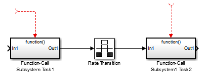
Handle Multiple Triggers for Function-Call Subsystem
When multiple interrupts trigger a function-call subsystem, the two triggering tasks must beset to the same priority. When the priority setting is the same, the outcome depends on whether the interrupts are triggered periodically or asynchronously and on a sample time diagnostic setting.
Consider this model:

This table and the footnotes that follow the table describe valid outcomes.
| Async Priority = 1 | Async Priority = 2 | Async Priority Unspecified | Periodic Priority = 1 | Periodic Priority = 2 | |
|---|---|---|---|---|---|
| Async Priority = 1 | Supported (1) | Not supported | Not supported | Not supported | Not supported |
| Async Priority = 2 | Not supported | Supported (1) | Not supported | Not supported | Not supported |
| Async Priority Unspecified | Not supported | Not supported | Supported (2) | Not supported | Not supported |
| Periodic Priority = 1 | Not supported | Not supported | Not supported | Supported | Not supported |
| Periodic Priority = 1 | Not supported | Not supported | Not supported | Not supported | Supported |
If tasks of equal priority cannot preempt each other in the target system, set the diagnostic model configuration parameter Tasks with equal priority to
none.Simulink returns this warning unconditionally:
The function call subsystem <name> has multiple asynchronous
triggers that do not specify priority. Data integrity will
not be maintained if these triggers can preemt one another.
The code generator provides absolute time management for a function-call subsystem connected to multiple triggers as in the preceding model where timer settings for TriggerA and TriggerB (time source and resolution) are the same.
Assume that these conditions are true for the preceding model:
A function-call subsystem is triggered by two asynchronous triggers (
TriggerAandTriggerB), which have the same priority setting.Each trigger sets the source of time and timer attributes by calling the functions
ssSetTimeSourceandssSetAsyncTimerAttributes.The triggered subsystem contains a block that needs elapsed or absolute time (for example, includes a Discrete Time Integrator block).
The asynchronous function-call subsystem has one global variable, clockTick#, where # is the task ID associated with the subsystem. This variable stores absolute time for the asynchronous task. There are two ways to handle timing:
If the time source is set to
SS_TIMESOURCE_BASERATE, the code generator produces timer code in the function produced for the function-call subsystem, updating the clock tick variable from the base rate clock tick. If the same priority is assigned toTriggerAandTriggerB, the generated code maintains data integrity.If the time source is set to
SS_TIMESOURCE_SELF, generated code forTriggerAandTriggerBupdates the same clock tick variable from the hardware clock.
You can set the word size of the clock tick variable directly or you can rely on the code generator to establish the word size based on the setting of model configuration parameter Application lifespan (days) and the timer resolution set by the TriggerA and TriggerB S-functions. These settings must be the same for the two S-functions. For more information, see 非同期タスクにおけるタイマー and Optimize Memory Usage and Prevent Overflows for Time Counters.
Data Integrity Protection and volatile Type Qualifier
When you select the Rate Transition block parameter Ensure data integrity during data transfer, the code generated for the block defines global buffers and semaphores to use for protecting the integrity of the transferred data.
For a multitasking application, the tasks (rates) involved in a data transfer can write data to buffers at times that your compiler cannot anticipate. To prevent the compiler from optimizing the assembly code in a manner that compromises the integrity of the transferred data, the code generator applies the volatile type qualifier to the buffers and semaphores. The code generator does not apply the type qualifier to the global variable that represents the transferred data because the volatile buffers and semaphores offer enough protection.
If you need to protect transferred data, for example, to protect data that external code shares with generated code, you can explicitly apply the type qualifier to the data by associating the signal line that connects the Rate Transition block to its source with a signal object. Then, set the object StorageClass property to Volatile.
Alternatively, to protect data that external code shares with generated code, you can write your own C functions that read and write the data in a protected manner. Then, you can set the object StorageClass property to GetSet, which causes the generated code to call your functions instead of directly accessing the data.
For more information about applying the volatile type qualifier, see 型修飾子 const と volatile を使用したグローバル データの保護 (Embedded Coder). For more information about the GetSet storage class, see Access Data Through Functions with Storage Class GetSet (Embedded Coder).
Influence Rate Transition Algorithm for Ensuring Determinism by Specifying Sample Time Options
For periodic tasks that have an offset of zero, have fast and slow rates that are multiples of each other, and the Rate Transition block parameter Ensure deterministic data transfer (maximum delay) is selected, the Rate Transition block controls the timing of a data transfer predictably. For example:
For fast-to-slow transitions, the Rate Transition block behaves like a Zero-Order Hold block.
For slow-to-fast transitions, the Rate Transition block behaves like a Unit Delay block.
You can influence the rate transition algorithm for ensuring determinism by changing the settings of Rate Transition block sample time parameters.
Choose how you want to specify the sample time of the Rate Transition output port by selecting a value for block parameter Output port sample time options.
To explicitly specify a sample time, which is the default option, select
Specify.To inherit the output sample time from the block to which the output port is connected, select
Inherit.To specify that the sample time of the output port is a multiple of the block input sample time, select
Multiple of input port sample time.
If you set parameter Output port sample time options to
SpecifyorMultiple of input port sample time, do one of the following:Set block parameter Output port sample time to the sample rate to which you want the Rate Transition block to convert its input port sample rate.
Set block parameter Sample time multiple (>0) to a positive value that is a multiple of the input port sample rate. For example, if you set the parameter to 0.5, the output port sample rate is half of the input port sample rate. If you set the parameter to 2, the output port rate is twice the input port rate.
For more information see, Rate Transition.
Rate Transition Blocks and Continuous Time
The sample time at the output port of a Rate Transition block must be discrete or fixed in minor time step. This means that when a Rate Transition block inherits continuous sample time from its destination block, it treats the inherited sample time as fixed in minor time step. Therefore, the output function of the Rate Transition block runs only at major time steps.
As this table shows, if the destination block sample time is continuous, the Rate Transition block output sample time depends on the type of solver configured for the model:
| Solver Type | Output Sample Time |
|---|---|
| Fixed-step | Base rate sample time |
| Variable-step | Zero-order-hold-continuous sample time |
Maintain Data Integrity When Data Transfer Read Can Occur Before Write
Depending on the scheduling of tasks for a component algorithm, a data transfer read can occur before a data transfer write. When this happens, the algorithm tries to read a value that does not exist yet or that is incorrect, which can lead to incorrect or unpredictable results. A way of maintaining the integrity of a data transfer is to specify initial condition values for blocks that are responsible for data transfer writes. The approach that you take for specifying initial conditions, depends on whether your component model is configured to use a data or service code interface.
Specify Initial Conditions for Models Configured that Use a Data Code Interface
For models that use a data code interface and rely on generated code for handling data transfers, a data transfer read can occur before a data transfer write for periodic slow-to-fast rate transitions. In this scenario, a Rate Transition block represents the data transfer. The Rate Transition block is ready to execute, but it has not yet received data from the slower block connected to its input port. To address this, you can use the Initial conditions parameter of a manually inserted Rate Transition block to specify initial condition values for the block. If the Rate Transition block has not received data at its input port by the start of execution, the block writes the specified initial condition value to its output port. The initial condition value that you specify must be a scalar, or must have the same dimensions as the input signal. The value cannot be Inf or NaN.
For more information, see Rate Transition.
Specify Initial Conditions for Models that Use Target Environment Data Transfer Services
For models that use a service code interface and rely on target platform data transfer services, consider using these initial condition approaches to address when a data transfer read occurs before a data transfer write:
| Modeling Style | Approach | Result |
|---|---|---|
| Rate-based | For manually inserted Rate Transition blocks or automatically inserted blocks that you choose to display in the model diagram, specify initial condition values for the Initial conditions parameter of that block. | The code generator produces data transfer set interface code in the model initialize entry-point function. |
For an automatically inserted Rate Transition block for which you choose to display just a block label, upstream from the label, place an IC block or another block that has an Initial conditions parameter and specify initial condition values. | The generated code passes the initial condition values to target platform software when that software calls the algorithm entry-point function. | |
| Export-function | Use one of these modeling patterns when setting up the data transfer signal:
| The code generator produces data transfer set interface code in the model initialize entry-point function. |
| Rate-based and export-function | Use an Initialize Function block to specify initial condition values. | The code generator produces data transfer set interface code in the model initialize entry-point function. If another source, such as a Merge block, binds the Initialize Function block to the subsystem that writes data for the data transfer, the model initialize entry-point function might call the data transfer set interface for each source. |
参考
Automatically handle rate transition for data transfer | Deterministic data transfer | Rate Transition | IC