このページの内容は最新ではありません。最新版の英語を参照するには、ここをクリックします。
類似性ベースの残存耐用期間推定
R2026aこの例では、残存耐用期間 (RUL) 推定の完全なワークフローを作成する方法を説明します。これには前処理、トレンドを示す特徴の選択、センサー融合による健康インジケーターの作成、類似性 RUL 推定器の学習、および予知性能の検証の手順が含まれます。ここでは、PHM2008 challenge データセットの学習データを使用します [1]。
データの準備
データセットは小さいので、劣化データ全体をメモリに読み込むことが可能です。データ セットをダウンロードして現在のディレクトリに解凍します。補助関数 helperLoadData を使用して学習テキスト ファイルを読み込み、timetable の cell 配列に変換します。学習データには、故障に至るまで実行された 260 回のシミュレーションのデータが含まれています。この計測値のグループを "アンサンブル" と呼びます。
url = 'https://ssd.mathworks.com/supportfiles/nnet/data/TurbofanEngineDegradationSimulationData.zip';
websave('TurbofanEngineDegradationSimulationData.zip',url);
unzip('TurbofanEngineDegradationSimulationData.zip')
degradationData = helperLoadData('train_FD002.txt');
degradationData(1:5)
ans=5×1 cell array
    149×26 table
    269×26 table
    206×26 table
    235×26 table
    154×26 table
各アンサンブル メンバーは 26 列の table です。列にはマシン ID、タイム スタンプ、3 つの動作状態、および 21 のセンサー測定値のデータが含まれます。
head(degradationData{1}) id time op_setting_1 op_setting_2 op_setting_3 sensor_1 sensor_2 sensor_3 sensor_4 sensor_5 sensor_6 sensor_7 sensor_8 sensor_9 sensor_10 sensor_11 sensor_12 sensor_13 sensor_14 sensor_15 sensor_16 sensor_17 sensor_18 sensor_19 sensor_20 sensor_21
__ ____ ____________ ____________ ____________ ________ ________ ________ ________ ________ ________ ________ ________ ________ _________ _________ _________ _________ _________ _________ _________ _________ _________ _________ _________ _________
1 1 34.998 0.84 100 449.44 555.32 1358.6 1137.2 5.48 8 194.64 2222.7 8341.9 1.02 42.02 183.06 2387.7 8048.6 9.3461 0.02 334 2223 100 14.73 8.8071
1 2 41.998 0.8408 100 445 549.9 1353.2 1125.8 3.91 5.71 138.51 2211.6 8304 1.02 42.2 130.42 2387.7 8072.3 9.3774 0.02 330 2212 100 10.41 6.2665
1 3 24.999 0.6218 60 462.54 537.31 1256.8 1047.5 7.05 9.02 175.71 1915.1 8001.4 0.94 36.69 164.22 2028 7864.9 10.894 0.02 309 1915 84.93 14.08 8.6723
1 4 42.008 0.8416 100 445 549.51 1354 1126.4 3.91 5.71 138.46 2211.6 8304 1.02 41.96 130.72 2387.6 8068.7 9.3528 0.02 329 2212 100 10.59 6.4701
1 5 25 0.6203 60 462.54 537.07 1257.7 1047.9 7.05 9.03 175.05 1915.1 7993.2 0.94 36.89 164.31 2028 7861.2 10.896 0.02 309 1915 84.93 14.13 8.5286
1 6 25.005 0.6205 60 462.54 537.02 1266.4 1048.7 7.05 9.03 175.17 1915.2 7996.1 0.94 36.78 164.27 2028 7868.9 10.891 0.02 306 1915 84.93 14.28 8.559
1 7 42.004 0.8409 100 445 549.74 1347.5 1127.2 3.91 5.71 138.71 2211.6 8307.8 1.02 42.19 130.49 2387.7 8075.5 9.3753 0.02 330 2212 100 10.62 6.4227
1 8 20.002 0.7002 100 491.19 607.44 1481.7 1252.4 9.35 13.65 334.41 2323.9 8709.1 1.08 44.27 315.11 2388 8049.3 9.2369 0.02 365 2324 100 24.33 14.799
劣化データを、学習データセットと、後で性能評価を行うための検証データセットに分割します。
rng('default')  % To make sure the results are repeatable
numEnsemble = length(degradationData);
numFold = 5;
cv = cvpartition(numEnsemble, 'KFold', numFold);
trainData = degradationData(training(cv, 1));
validationData = degradationData(test(cv, 1));
対象とする変数のグループを指定します。
varNames = string(degradationData{1}.Properties.VariableNames);
timeVariable = varNames{2};
conditionVariables = varNames(3:5);
dataVariables = varNames(6:26);
アンサンブル データのサンプルを可視化します。
nsample = 10;
figure
helperPlotEnsemble(trainData, timeVariable, ...
    [conditionVariables(1:2) dataVariables(1:2)], nsample)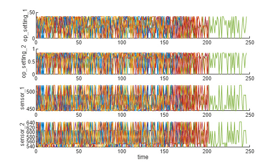
作業領域クラスタリング
前の節で示したように、故障に至るまで実行された各測定データにおいて劣化プロセスを示す明確なトレンドはありません。この節と次の節では、動作状態を使用してより明確な劣化トレンドをセンサー信号から抽出します。
各アンサンブル メンバーには、"op_setting_1"、"op_setting_2"、"op_setting_3" の 3 つの動作状態が含まれています。まず、各 cell から table を抽出して単一の table に連結します。
trainDataUnwrap = vertcat(trainData{:});
opConditionUnwrap = trainDataUnwrap(:, cellstr(conditionVariables));
すべての操作点を 3 次元散布図に可視化します。明らかに 6 つの領域が示されており、各領域内の点は非常に近接しています。
figure
helperPlotClusters(opConditionUnwrap)
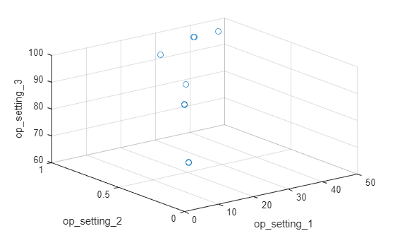
クラスタリング手法を使って 6 つのクラスターを自動的に検出してみましょう。ここでは k-means アルゴリズムを使用します。k-means は最もよく使われるクラスタリング アルゴリズムの 1 つですが、結果が局所的な最適値となる場合があります。k-means クラスタリング アルゴリズムを異なった初期状態で何度か繰り返し、コストが最も低い結果を選択することをお勧めします。ここではアルゴリズムが 5 回実行され、同じ結果となっています。
opts = statset('Display', 'final');
[clusterIndex, centers] = kmeans(table2array(opConditionUnwrap), 6, ...
    'Distance', 'sqeuclidean', 'Replicates', 5, 'Options', opts);
Replicate 1, 1 iterations, total sum of distances = 0.331378.
Replicate 2, 1 iterations, total sum of distances = 0.331378.
Replicate 3, 1 iterations, total sum of distances = 0.331378.
Replicate 4, 1 iterations, total sum of distances = 0.331378.
Replicate 5, 1 iterations, total sum of distances = 0.331378.
Best total sum of distances = 0.331378
クラスタリングの結果と特定されたクラスター重心を可視化します。
figure
helperPlotClusters(opConditionUnwrap, clusterIndex, centers)

プロットに示されているように、クラスタリング アルゴリズムで 6 つの作業領域が正しく検出されます。
作業領域の正規化
異なる作業領域でグループ化された測定値について正規化を実行しましょう。最初に、前の節で検出した作業領域によってグループ化された各センサー測定値の平均と標準偏差を計算します。
centerstats = struct('Mean', table(), 'SD', table());
for v = dataVariables
    centerstats.Mean.(char(v)) = splitapply(@mean, trainDataUnwrap.(char(v)), clusterIndex);
    centerstats.SD.(char(v))   = splitapply(@std,  trainDataUnwrap.(char(v)), clusterIndex);
end
centerstats.Mean
ans=6×21 table
    489.0500    604.9094    1.5020e+03    1.3112e+03    10.5200    15.4933    394.3264    2.3190e+03    8.7858e+03    1.2600    45.4869    371.4472    2.3882e+03    8.1355e+03     8.6645    0.0300    369.6923    2319        100    28.5273    17.1155
    462.5400    536.8592    1.2627e+03    1.0502e+03     7.0500     9.0277    175.4310    1.9154e+03    8.0156e+03    0.9399    36.7983    164.5749    2.0283e+03    7.8786e+03    10.9134    0.0200    307.3386    1915    84.9300    14.2633     8.5587
         445    549.7039    1.3544e+03    1.1277e+03     3.9100     5.7158    138.6336    2.2120e+03    8.3281e+03    1.0202    42.1460    130.5532    2.3881e+03    8.0897e+03     9.3745    0.0200    331.0583    2212        100    10.5880     6.3516
    491.1900    607.5606    1.4855e+03    1.2530e+03     9.3500    13.6566    334.5001    2.3240e+03    8.7300e+03    1.0777    44.4460    314.8797    2.3882e+03    8.0661e+03     9.2325    0.0221    365.3689    2324        100    24.4549    14.6738
    518.6700    642.6744    1.5903e+03    1.4087e+03    14.6200    21.6098    553.3719    2.3881e+03    9.0633e+03    1.3000    47.5383    521.4148    2.3881e+03    8.1420e+03     8.4419    0.0300    393.1829    2388        100    38.8195    23.2916
    449.4400    555.7971    1.3667e+03    1.1315e+03     5.4800     8.0003    194.4480    2.2230e+03    8.3564e+03    1.0204    41.9809    183.0256    2.3881e+03    8.0725e+03     9.3319    0.0200    334.2246    2223        100    14.8307     8.8983
centerstats.SD
ans=6×21 table
    1.0346e-11    0.4758    5.8057    8.5359    3.2687e-13    0.0047    0.6736    0.0953    18.8192    1.7552e-04    0.2538    0.5362    0.0982    16.5074    0.0384    6.6965e-16    1.4900    0             0    0.1444    0.0860
    4.6615e-12    0.3608    5.2850    6.8365    1.1370e-13    0.0042    0.4486    0.2701    14.4793    8.7595e-04    0.2084    0.3449    0.2859    13.4274    0.0433    3.4003e-16    1.2991    0    3.5246e-12    0.1122    0.0664
             0    0.4328    5.6422    7.6564    1.1014e-13    0.0049    0.4397    0.3048    18.3251        0.0016    0.2396    0.3401    0.3286    16.7729    0.0375    1.0652e-15    1.4114    0             0    0.1083    0.0647
    1.8362e-11    0.4634    5.7888    7.7768    2.5049e-13    0.0047    0.6046    0.1283    17.5800        0.0042    0.2383    0.4984    0.1316    15.4567    0.0389        0.0041    1.4729    0             0    0.1353    0.0796
    1.2279e-11    0.4967    6.0349    8.9734    6.5730e-14    0.0013    0.8699    0.0708    19.8890    2.7314e-14    0.2651    0.7371    0.0705    17.1049    0.0373    6.6619e-16    1.5332    0             0    0.1787    0.1065
    1.4098e-11    0.4401    5.6013    7.4461    2.2828e-13    0.0018    0.4756    0.2863    17.4460        0.0020    0.2308    0.3763    0.3077    15.8250    0.0381    3.3656e-16    1.4133    0             0    0.1135    0.0672
各領域の統計値を使用して学習データを正規化することができます。各アンサンブル メンバーについて、各行の操作点を抽出し、その各クラスター中心までの距離を計算して、最も近いクラスター中心を見つけます。次に、各センサー測定値について、平均を減算し、そのクラスターの標準偏差で除算します。標準偏差が 0 に近い場合は、正規化されたセンサー測定値を 0 に設定します。これは、ほぼ一定のセンサー測定値は残存耐用期間の推定に有用でないためです。関数 regimeNormalization の詳細については、最後の節である「補助関数」を参照してください。
trainDataNormalized = cellfun(@(data) regimeNormalization(data, centers, centerstats), ...
    trainData, 'UniformOutput', false);
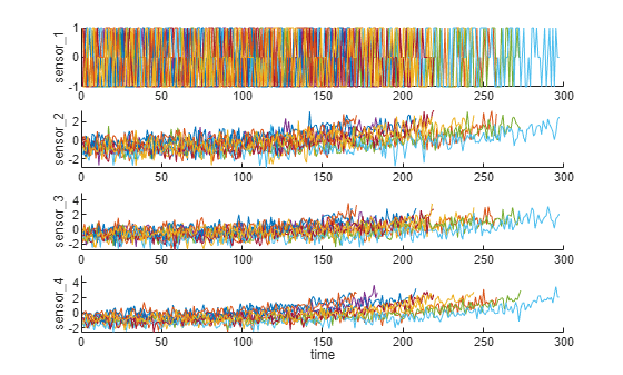
作業領域で正規化されたデータを可視化します。一部のセンサー測定値における劣化のトレンドが正規化の後で明らかになっています。
figure
helperPlotEnsemble(trainDataNormalized, timeVariable, dataVariables(1:4), nsample)
トレンド可能性の解析
次に、トレンドを最もよく示すセンサー測定値を選択して、予測のための健康インジケーターを作成します。各センサー測定値について、線形劣化モデルを推定して信号の傾きをランク付けします。
numSensors = length(dataVariables);
signalSlope = zeros(numSensors, 1);
warn = warning('off');
for ct = 1:numSensors
    tmp = cellfun(@(tbl) tbl(:, cellstr(dataVariables(ct))), trainDataNormalized, 'UniformOutput', false);
    mdl = linearDegradationModel(); % create model
    fit(mdl, tmp); % train mode
    signalSlope(ct) = mdl.Theta;
end
warning(warn);
信号の傾きを並べ替え、傾きが最も大きい 8 つのセンサーを選択します。
[~, idx] = sort(abs(signalSlope), 'descend');
sensorTrended = sort(idx(1:8))
sensorTrended = 8×1
2
3
4
7
11
12
15
17
選択された、トレンドを示すセンサー測定値を可視化します。
figure
helperPlotEnsemble(trainDataNormalized, timeVariable, dataVariables(sensorTrended(3:6)), nsample)

トレンドを最もよく示す信号のいくつかは正のトレンドですが、他は負のトレンドである点に注意してください。
健康インジケーターの作成
この節では、センサー測定値を単一の健康インジケーターに融合させる作業に焦点を当てます。インジケーターは類似性ベースのモデルの学習に使用されます。
故障に至るまで実行されたすべてのデータは、健全な状態から開始されると仮定します。初期の健康状態には 1 の値が割り当てられ、故障時の健康状態には 0 の値が割り当てられます。健康状態は時間とともに 1 から 0 へ線形に劣化すると仮定されます。この線形劣化を利用して、センサー測定値の融合を行います。より高度なセンサー融合手法については、文献 [2-5] で説明されています。
for j=1:numel(trainDataNormalized)
    data = trainDataNormalized{j};
    rul = max(data.time)-data.time;
    data.health_condition = rul / max(rul);
    trainDataNormalized{j} = data;
end
健康状態を可視化します。
figure
helperPlotEnsemble(trainDataNormalized, timeVariable, "health_condition", nsample)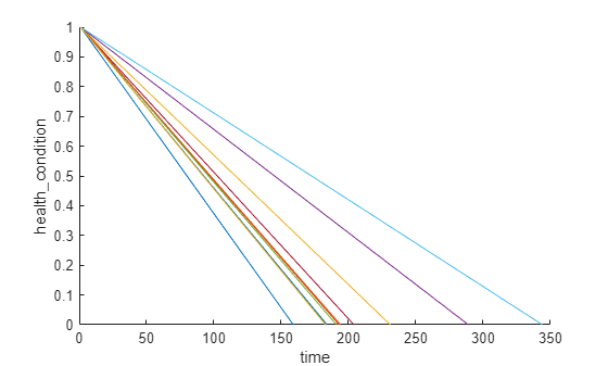
すべてのアンサンブル メンバーの健康状態が、さまざまな劣化速度で 1 から 0 に変化します。
次に、Health Condition の線形回帰モデルを、トレンドを最もよく示すセンサー測定値にリグレッサーとして当てはめます。
Health Condition ~ 1 + Sensor2 + Sensor3 + Sensor4 + Sensor7 + Sensor11 + Sensor12 + Sensor15 + Sensor17
trainDataNormalizedUnwrap = vertcat(trainDataNormalized{:});

sensorToFuse = dataVariables(sensorTrended);
X = trainDataNormalizedUnwrap{:, cellstr(sensorToFuse)};
y = trainDataNormalizedUnwrap.health_condition;
regModel = fitlm(X,y);
bias = regModel.Coefficients.Estimate(1)
bias = 0.5000
weights = regModel.Coefficients.Estimate(2:end)
weights = 8×1

    -0.0323
    -0.0300
    -0.0527
     0.0057
    -0.0646
     0.0054
    -0.0431
    -0.0379
センサー測定値をその関連する重みで乗算し、単一の健康インジケーターを作成します。
trainDataFused = cellfun(@(data) degradationSensorFusion(data, sensorToFuse, weights), trainDataNormalized, ...
    'UniformOutput', false);
融合された健康インジケーターを学習データについて可視化します。
figure
helperPlotEnsemble(trainDataFused, [], 1, nsample)
xlabel('Time')
ylabel('Health Indicator')
title('Training Data')
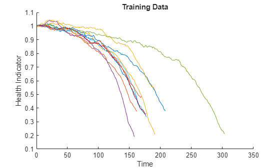
複数のセンサーからのデータが単一の健康インジケーターに融合されます。健康インジケーターは、移動平均フィルターで平滑化されています。詳細については、最後の節にある補助関数 "degradationSensorFusion" を参照してください。
検証データへの同じ操作の適用
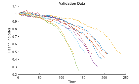
領域の正規化とセンサー融合のプロセスを検証データセットで繰り返します。
validationDataNormalized = cellfun(@(data) regimeNormalization(data, centers, centerstats), ...
    validationData, 'UniformOutput', false);
validationDataFused = cellfun(@(data) degradationSensorFusion(data, sensorToFuse, weights), ...
    validationDataNormalized, 'UniformOutput', false);
健康インジケーターを検証データについて可視化します。
figure
helperPlotEnsemble(validationDataFused, [], 1, nsample)
xlabel('Time')
ylabel('Health Indicator')
title('Validation Data')
類似性 RUL モデルの作成
次に、学習データを使用して残差ベースの類似性 RUL モデルを作成します。この設定では、モデルは各融合データを 2 次多項式に当てはめようとします。
データ とデータ 間の距離は、残差の 1 ノルムにより計算されます。
ここで、 はマシン の健康インジケーターであり、 はマシン で同定された 2 次多項式モデルを使用する、マシン の推定された健康インジケーターです。
類似性スコアは次の式で計算されます。
検証データセット内の 1 つのアンサンブル メンバーについて、モデルは学習データセット内の最も近い 50 個のアンサンブル メンバーを見つけ、50 個のアンサンブル メンバーに基づいて確率分布を当てはめ、分布の中央値を RUL の推定値として使用します。
mdl = residualSimilarityModel(...
    'Method', 'poly2',...
    'Distance', 'absolute',...
    'NumNearestNeighbors', 50,...
    'Standardize', 1);

fit(mdl, trainDataFused);
性能の評価
類似性 RUL モデルを評価するには、50%、70%、90% のサンプル検証データを使用してその RUL を予測します。
breakpoint = [0.5, 0.7, 0.9];
validationDataTmp = validationDataFused{3}; % use one validation data for illustration
寿命の 50% である最初のブレークポイントより前の検証データを使用します。
bpidx = 1;
validationDataTmp50 = validationDataTmp(1:ceil(end*breakpoint(bpidx)),:);
trueRUL = length(validationDataTmp) - length(validationDataTmp50);
[estRUL, ciRUL, pdfRUL] = predictRUL(mdl, validationDataTmp50);
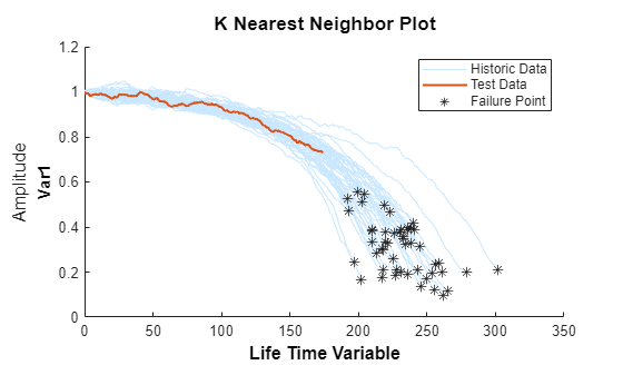
50% で打ち切られた検証データとその最近傍を可視化します。
figure
compare(mdl, validationDataTmp50);

真の RUL と比較した推定 RUL と、推定 RUL の確率分布を可視化します。
figure
helperPlotRULDistribution(trueRUL, estRUL, pdfRUL, ciRUL)
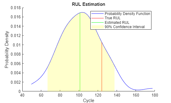
マシンが中間の健全性段階にある場合、推定された RUL と真の RUL の間には比較的大きな誤差があります。この例では、最も類似した 10 個の曲線が最初は近接していますが、故障状態に近づくにつれて分岐し、結果として RUL 分布でおよそ 2 つの最頻値となります。
寿命の 70% である 2 番目のブレークポイントより前の検証データを使用します。
bpidx = 2;
validationDataTmp70 = validationDataTmp(1:ceil(end*breakpoint(bpidx)), :);
trueRUL = length(validationDataTmp) - length(validationDataTmp70);
[estRUL,ciRUL,pdfRUL] = predictRUL(mdl, validationDataTmp70);

figure
compare(mdl, validationDataTmp70);
figure
helperPlotRULDistribution(trueRUL, estRUL, pdfRUL, ciRUL)
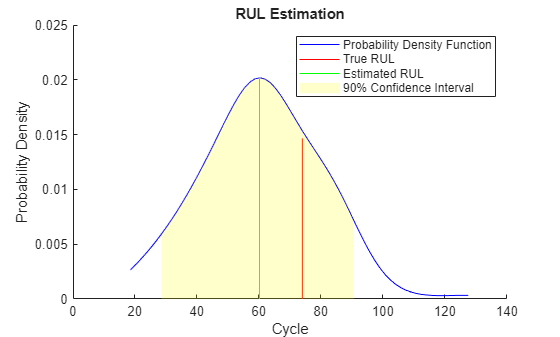
観測されるデータが増えるにつれて、RUL の推定は改善されます。
寿命の 90% である 3 番目のブレークポイントより前の検証データを使用します。
bpidx = 3;
validationDataTmp90 = validationDataTmp(1:ceil(end*breakpoint(bpidx)), :);
trueRUL = length(validationDataTmp) - length(validationDataTmp90);
[estRUL,ciRUL,pdfRUL] = predictRUL(mdl, validationDataTmp90);

figure
compare(mdl, validationDataTmp90);

figure
helperPlotRULDistribution(trueRUL, estRUL, pdfRUL, ciRUL)
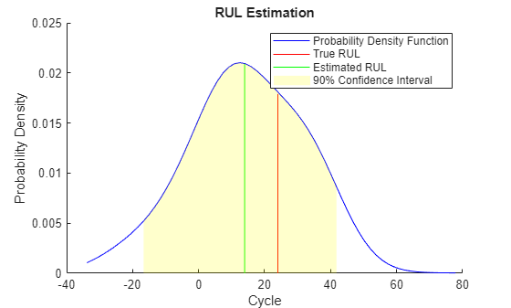
マシンが故障に近づくと、この例では RUL の推定がさらに改善されます。
ここで、同じ評価手順を検証データセット全体に対して繰り返し、推定された RUL と真の RUL の間の誤差を各ブレークポイントについて計算します。
numValidation = length(validationDataFused);
numBreakpoint = length(breakpoint);
error = zeros(numValidation, numBreakpoint);

for dataIdx = 1:numValidation
    tmpData = validationDataFused{dataIdx};
    for bpidx = 1:numBreakpoint
        tmpDataTest = tmpData(1:ceil(end*breakpoint(bpidx)), :);
        trueRUL = length(tmpData) - length(tmpDataTest);
        [estRUL, ~, ~] = predictRUL(mdl, tmpDataTest);
        error(dataIdx, bpidx) = estRUL - trueRUL;
    end
end
各ブレークポイントの誤差のヒストグラムを、その確率分布とともに可視化します。
[pdf50, x50] = ksdensity(error(:, 1));
[pdf70, x70] = ksdensity(error(:, 2));
[pdf90, x90] = ksdensity(error(:, 3));

figure
ax(1) = subplot(3,1,1);
hold on
histogram(error(:, 1), 'BinWidth', 5, 'Normalization', 'pdf')
plot(x50, pdf50)
hold off
xlabel('Prediction Error')
title('RUL Prediction Error using first 50% of each validation ensemble member')

ax(2) = subplot(3,1,2);
hold on
histogram(error(:, 2), 'BinWidth', 5, 'Normalization', 'pdf')
plot(x70, pdf70)
hold off
xlabel('Prediction Error')
title('RUL Prediction Error using first 70% of each validation ensemble member')

ax(3) = subplot(3,1,3);
hold on
histogram(error(:, 3), 'BinWidth', 5, 'Normalization', 'pdf')
plot(x90, pdf90)
hold off
xlabel('Prediction Error')
title('RUL Prediction Error using first 90% of each validation ensemble member')
linkaxes(ax)
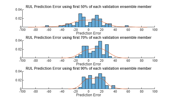
予測誤差を箱ひげ図にプロットして中央値、25 ~ 75 分位数、および外れ値を可視化します。
figure
boxplot(error, 'Labels', {'50%', '70%', '90%'})
ylabel('Prediction Error')
title('Prediction error using different percentages of each validation ensemble member')
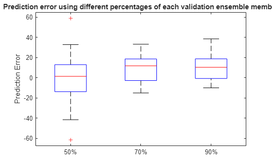
予測誤差の平均と標準偏差を計算して可視化します。
errorMean = mean(error)
errorMean = 1×3

    -1.1217    9.5186    9.6540
errorMedian = median(error)
errorMedian = 1×3

    1.3798    11.8172    10.3457
errorSD = std(error)
errorSD = 1×3

    21.7315    13.5194    12.3083
figure
errorbar([50 70 90], errorMean, errorSD, '-o', 'MarkerEdgeColor','r')
xlim([40, 100])
xlabel('Percentage of validation data used for RUL prediction')
ylabel('Prediction Error')
legend('Mean Prediction Error with 1 Standard Deviation Error bar', 'Location', 'south')
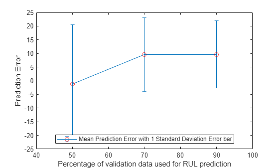
観察されるデータが増えるにつれて、誤差は 0 付近に集中する (外れ値が少ない) ことが示されています。
参考文献
[1] A. Saxena and K. Goebel (2008)."PHM08 Challenge Data Set", NASA Ames Prognostics Data Repository (http://ti.arc.nasa.gov/project/prognostic-data-repository), NASA Ames Research Center, Moffett Field, CA
[2] Roemer, Michael J., Gregory J. Kacprzynski, and Michael H. Schoeller."Improved diagnostic and prognostic assessments using health management information fusion."AUTOTESTCON Proceedings, 2001.IEEE Systems Readiness Technology Conference.IEEE, 2001.
[3] Goebel, Kai, and Piero Bonissone."Prognostic information fusion for constant load systems."Information Fusion, 2005 8th International Conference on.Vol. 2.IEEE, 2005.
[4] Wang, Peng, and David W. Coit."Reliability prediction based on degradation modeling for systems with multiple degradation measures."Reliability and Maintainability, 2004 Annual Symposium-RAMS.IEEE, 2004.
[5] Jardine, Andrew KS, Daming Lin, and Dragan Banjevic."A review on machinery diagnostics and prognostics implementing condition-based maintenance."Mechanical systems and signal processing 20.7 (2006):1483-1510.
補助関数
function data = regimeNormalization(data, centers, centerstats)
% Perform normalization for each observation (row) of the data
% according to the cluster the observation belongs to.
conditionIdx = 3:5;
dataIdx = 6:26;

% Perform row-wise operation
data{:, dataIdx} = table2array(...
    rowfun(@(row) localNormalize(row, conditionIdx, dataIdx, centers, centerstats), ...
    data, 'SeparateInputs', false));
end

function rowNormalized = localNormalize(row, conditionIdx, dataIdx, centers, centerstats)
% Normalization operation for each row.

% Get the operating points and sensor measurements
ops = row(1, conditionIdx);
sensor = row(1, dataIdx);

% Find which cluster center is the closest
dist = sum((centers - ops).^2, 2);
[~, idx] = min(dist);

% Normalize the sensor measurements by the mean and standard deviation of the cluster.
% Reassign NaN and Inf to 0.
rowNormalized = (sensor - centerstats.Mean{idx, :}) ./ centerstats.SD{idx, :};
rowNormalized(isnan(rowNormalized) | isinf(rowNormalized)) = 0;
end

function dataFused = degradationSensorFusion(data, sensorToFuse, weights)
% Combine measurements from different sensors according
% to the weights, smooth the fused data and offset the data
% so that all the data start from 1

% Fuse the data according to weights
dataToFuse = data{:, cellstr(sensorToFuse)};
dataFusedRaw = dataToFuse*weights;

% Smooth the fused data with moving mean
stepBackward = 10;
stepForward = 10;
dataFused = movmean(dataFusedRaw, [stepBackward stepForward]);

% Offset the data to 1
dataFused = dataFused + 1 - dataFused(1);
end

